Exercise machine rail system
a technology for exercise machines and rail systems, applied in gymnastic exercise, resilient force resistors,stilts, etc., can solve problems such as injury of exercisers, inadequate base structure, and legal claims against pilates studios
- Summary
- Abstract
- Description
- Claims
- Application Information
AI Technical Summary
Benefits of technology
Problems solved by technology
Method used
Image
Examples
first embodiment
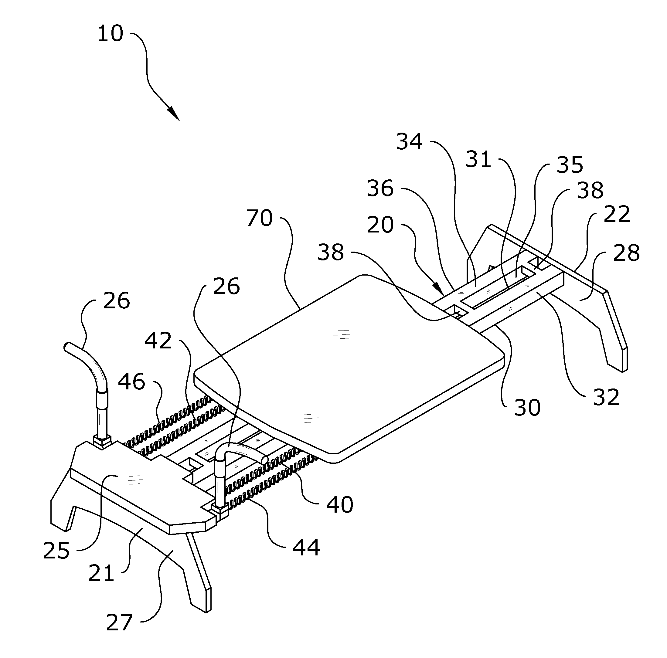
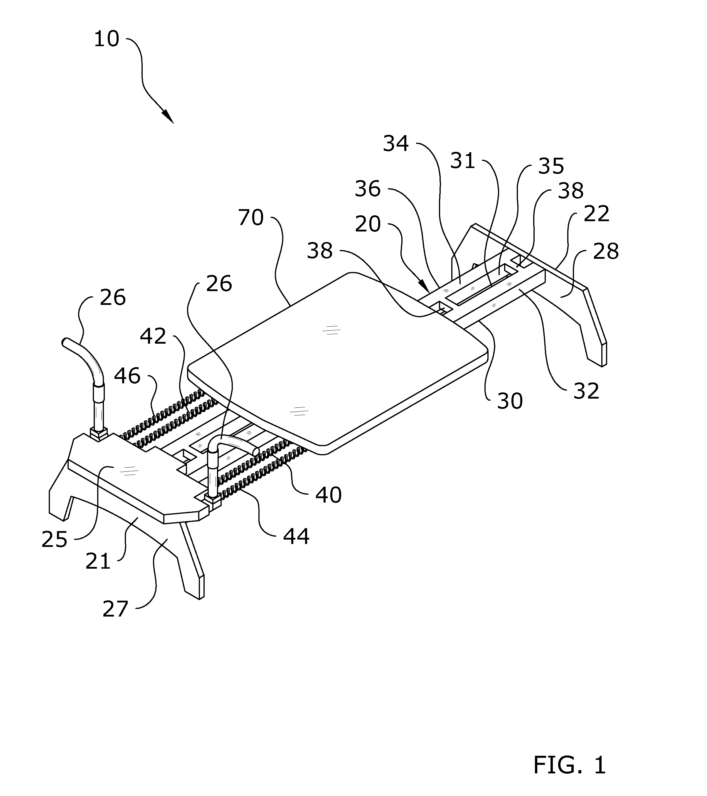
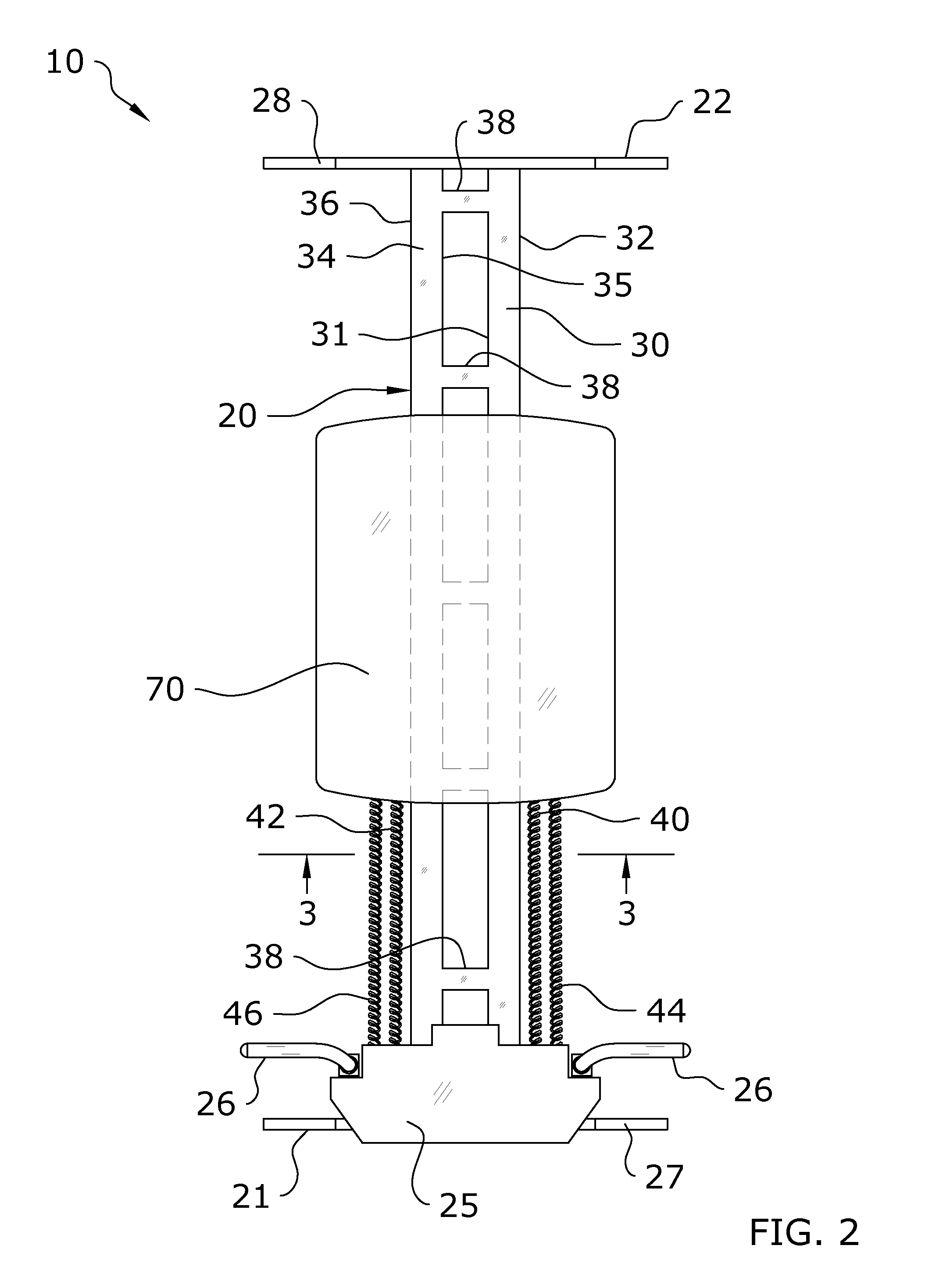
[0063]FIGS. 1-4 illustrate the present invention in which a pair of rails 30, 34 extend in close spaced-apart relationship with each other between the first end 21 and the second end 22 of the exercise machine 20. It is preferable that the rails 30, 34 be minimally spaced from each other so that, taken together, the pair of rails 30, 34 comprise a narrow structure which is easy to straddle or walk around for an exerciser 11. The carriage 70 is adapted to move, such as by sliding, along the pair of rails 30, 34 through various methods known in the art for moving a carriage 70 along rails 30, 34.
[0064]In the first embodiment of the present invention, the first rail 30 and second rail 34 extend parallel with respect to each other. The first rail 30 includes a first interior side 31 which faces toward the second rail 34 and a first exterior side 32 which faces away from the second rail 34. Similarly, the second rail 34 includes a second interior side 35 which faces toward the first rail...
second embodiment
[0072]FIGS. 5-10 illustrate the present invention which utilizes a single rail 50 which is centrally positioned along the longitudinal axis of the exercise machine 20 and bias members 40, 42, 44, 46 positioned laterally to the singular rail 50. The rail 50 extends between the first end 21 and the second end 22 of the exercise machine 20. The rail 50 includes an upper end 51, a lower end 52, a first side 53, and a second side 54.
[0073]The rail 50 may comprise various configurations, but will preferably comprise an I-shaped cross-section as shown in the figures, with the rail 50 comprising an I-beam. With such a configuration, the rail 50 includes a first channel 56 extending along its first side 53 and a second channel 57 extending along its second side 54.
[0074]The interconnection between the carriage 70 and the rail 50 is best shown in FIG. 8. Generally, one or more wheels 76, 77, 78, 79 will extend down from the carriage 70, such as by usage of a lower bracket 71, to engage with t...
third embodiment
[0085]FIGS. 11-14 illustrate the present invention which utilizes a single rail 50 which is centrally positioned along the longitudinal axis of the exercise machine 20 and bias members 40, 42, 44, 46 internally to the singular rail 50. The rail 50 extends between the first end 21 and the second end 22 of the exercise machine 20. The rail 50 includes an upper end 51, a lower end 52, a first side 53, and a second side 54. Additionally, in this embodiment, the rail 50 is substantially hollow with an internal channel 60 extending therethrough between its first and second ends 53, 54. The rail 50 may also include an upper slot 59 through which the lower bracket 71 will extend to link the carriage 70 with a bias mount 72 kept internal to the rail 50. In this embodiment of the present invention, the bias members 40, 42, 44, 46 extend through the internal channel 60 of the rail 50 as shown in FIG. 12.
[0086]As can be readily seen in the drawings, the internal channel 60 of the rail 50 furthe...
PUM
 Abstract
Description
Claims
Application Information
 - R&D
- Intellectual Property
- Life Sciences
- Materials
- Tech Scout
- Unparalleled Data Quality
- Higher Quality Content
- 60% Fewer Hallucinations
Browse by: Latest US Patents, China's latest patents, Technical Efficacy Thesaurus, Application Domain, Technology Topic, Popular Technical Reports.
© 2025 PatSnap. All rights reserved.Legal|Privacy policy|Modern Slavery Act Transparency Statement|Sitemap|About US| Contact US: help@patsnap.com


