
Alarm detector

a technology of alarm detector and sounder, which is applied in the direction of fire alarm, electric/electromagnetic audible signalling, instruments, etc., can solve the problems of not being able to meet these requirements, and achieve the effect of improving the sound intensity of alarm detector and improving the sound intensity of alarm sounders

Active Publication Date: 2017-03-07
SIEMENS SWITZERLAND
View PDF7 Cites 0 Cited by
  • Summary
  • Abstract
  • Description
  • Claims
  • Application Information

AI Technical Summary

Benefits of technology

[0008]In view of this, the alarm detector improves the sound intensity of the alarm detector.
[0015]It can be seen from the above-mentioned solutions that since in the embodiments of a sound amplification component having at least one horn shaped channel is disposed at a sound-making end of an alarm sounder in an alarm detector, and a throat end of the horn shaped channel of the sound amplification component is made to correspond to the sound-making end of the alarm sounder, the sound intensity of the alarm sounder can be improved. Further, the sound intensity of the alarm detector in the embodiments can also meet the regulations of the industry standards.
[0016]Furthermore, in the embodiments, an outlet end of a large horn channel is provided with a plurality of grilles such that the outlet end forms a plurality of sub-outlets, with each of the sub-outlets being in a horn shape, so that the sound intensity of an alarm detector can be further improved.

Problems solved by technology

However, no matter what kind of alarm detector is used, the sound intensity thereof is usually limited by a specific component and will not reach a higher volume; therefore, for some applications with special requirements, for example, waking up people in deep sleep by an alarm sound, etc., this may not be enough to meet these requirements.

Method used


Image

  • Alarm detector
  • Alarm detector
  • Alarm detector

Examples


first embodiment

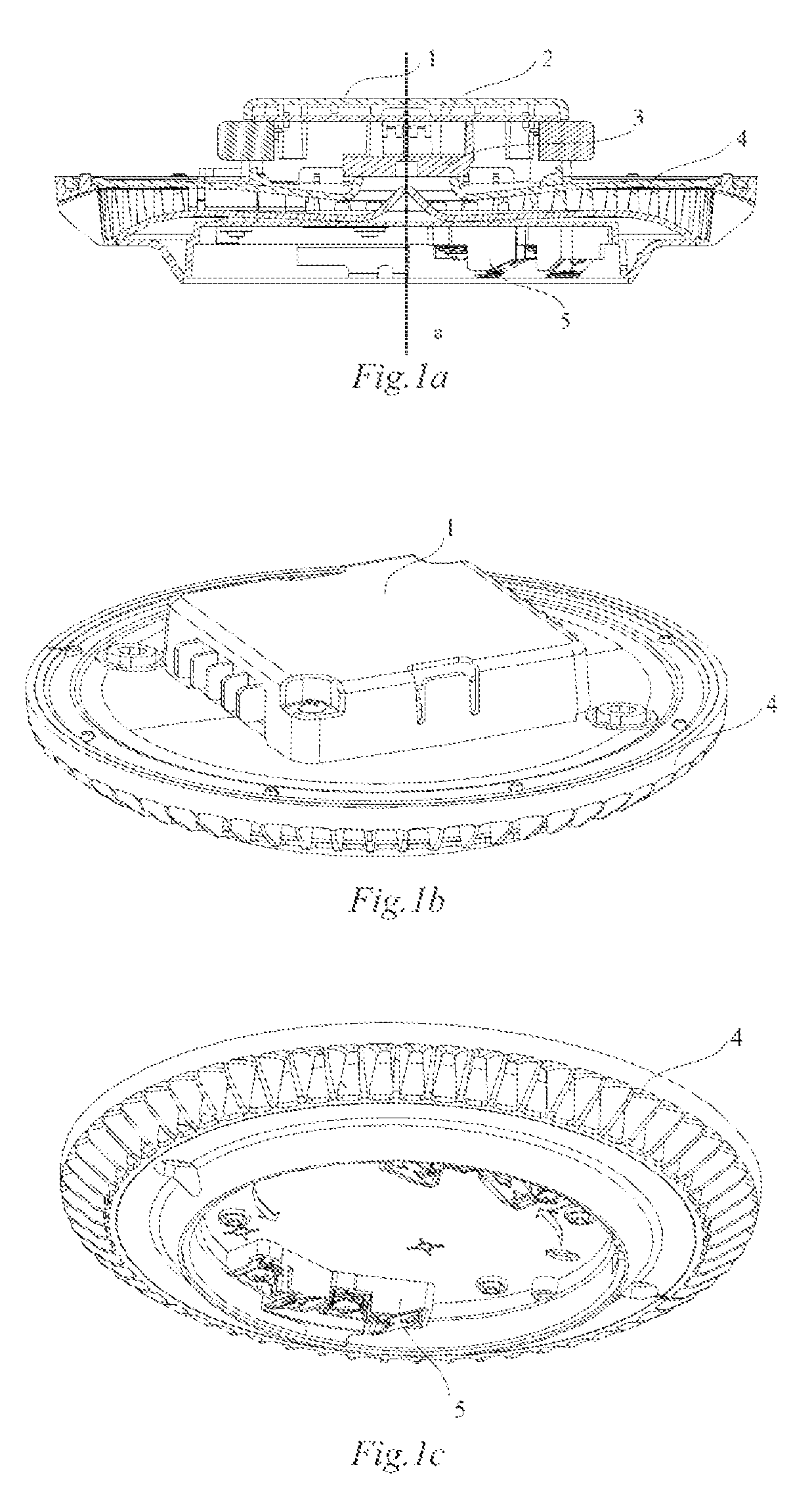
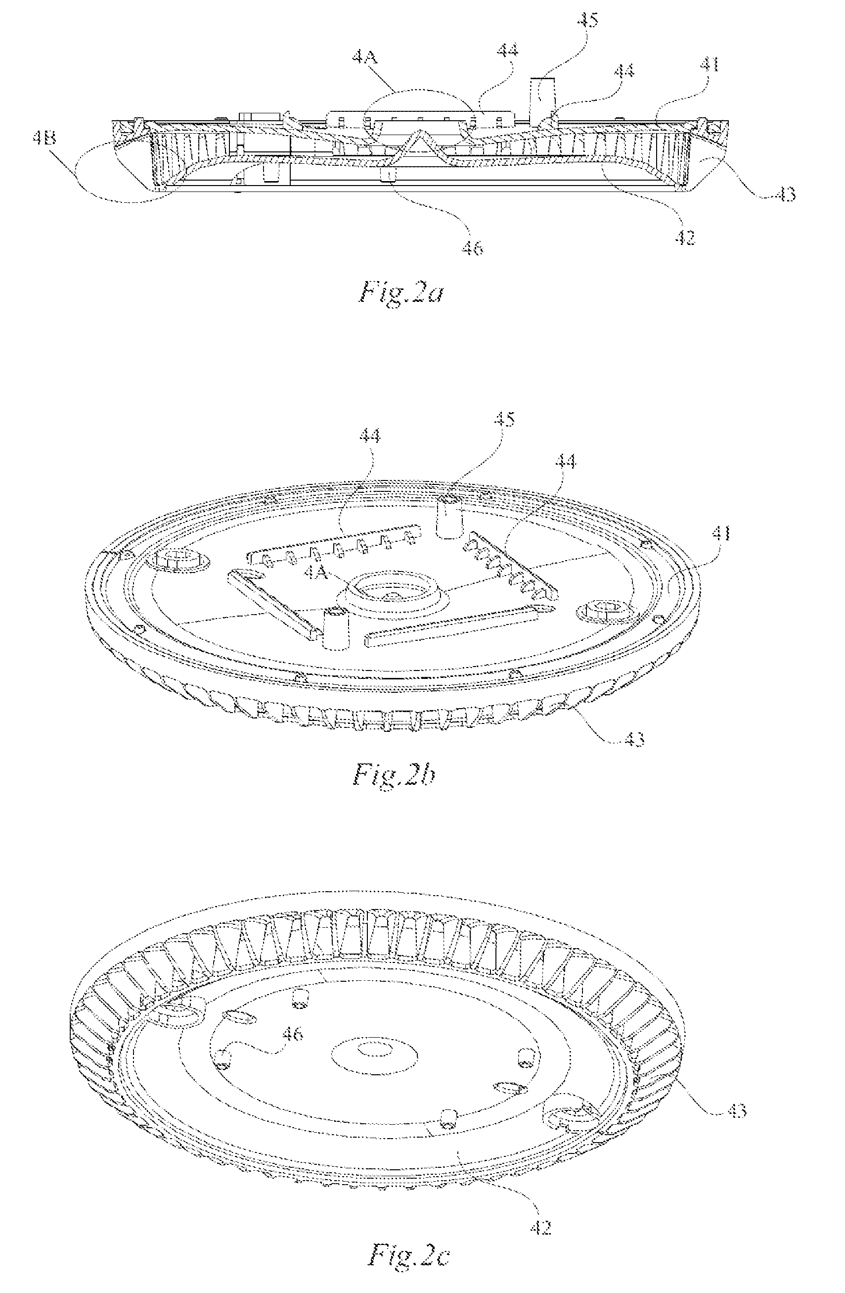
[0026]FIGS. 1a to 1c are structural schematic representations of an alarm detector in a first embodiment. FIG. 1a is a full sectional view of a front view, FIG. 1b is a perspective top view, and FIG. 1c is a perspective bottom view. FIGS. 2a to 2d are structural schematic representations of a sound amplification component in the alarm detector shown in FIGS. 1a to 1c. FIG. 2a is a full sectional view of a front view, FIG. 2b is a perspective top view, FIG. 2c is a perspective bottom view, and FIG. 2d is a partially enlarged plan view of an outlet end of the sound amplification component. Unless specifically explained, the orientations, such as upper, lower, left, right and so on, involved in the descriptive embodiments to facilitate the explanation, are all based on the viewing angle shown in FIG. 1a.

[0027]As shown in FIG. 1a to FIG. 2d, the alarm detector includes: a circuit cover plate 1, a circuit board 2, a buzzer 3 mounted on the circuit board 2, a sound amplification componen...

second embodiment

[0038]FIGS. 3a to 3c are structural schematic representations of an alarm detector in a second embodiment. FIG. 3a is a full sectional view of a front view, FIG. 3b is a top view, and FIG. 3c is a bottom view. FIGS. 4a to 4c are structural schematic representations of a sound amplification component in the alarm detector as shown in FIGS. 3a to 3c. FIG. 4a is a full sectional view of a front view, FIG. 4b is a perspective top view, and FIG. 4c is a perspective bottom view.

[0039]As shown in FIGS. 3a to 4c, the alarm detector includes: a circuit cover plate 6, a circuit board 7, a speaker 8 mounted on the circuit board 7, a sound amplification component 9 and a sensor base 10. Furthermore, the alarm detector can also include a sensor (not shown).

[0040]Similarly to the alarm detector as shown in FIGS. 1a to 2c, the sound amplification component 9 in the second embodiment can also be implemented in a multiplicity of specific structures, and it may have only one horn channel, or may have...


PUM


Abstract

An alarm sounder and at least one sound amplification component having at least one horn shaped channel form an alarm detector. The at least one horn shaped channel has a throat end and an outlet end, the throat end being disposed corresponding to a sound-making end of the alarm sounder. The sound intensity of the alarm detector can meet the regulations of the industry standards.

Description

CROSS REFERENCE TO RELATED APPLICATIONS[0001]This application is based on and hereby claims priority to Chinese Application No. 201310064993.4 filed on Feb. 28, 2013, the contents of which are hereby incorporated by reference herein in their entirety.BACKGROUND[0002]Technical Field[0003]The field is safety precaution, and in particular, alarm detector.[0004]Background Art[0005]An alarm detector is, as a sensing and detecting device, used for detecting various abnormal situations as well as the intrusion behavior of an intruder. A number of locations in a variety of intelligent buildings and general buildings are in need of safety precaution, and these locations have a variety of purposes and requirements of safety precaution according to actual situations. Therefore, there exists a need for a variety of alarm detectors, such as a smoke detector, a temperature detector, a special gas detector and an intrusion detector and the like, to meet different requirements of safety precaution....

Claims


Application Information

Patent Timeline
Patent Type & Authority Patents(United States)
IPC IPC(8): G08B3/10G08B17/113G08B17/00
CPCG08B3/10G08B17/113G08B17/00
Inventor SUN, CHANG LIN
Owner SIEMENS SWITZERLAND
Learn More