Double-row roller bearing

a roller bearing and double-row technology, applied in the direction of bearings, shafts and bearings, rotary machine parts, etc., can solve the problems of affecting the smooth rotational movement between the thickness of the outer ring needs to be increased, and the increase in the temperature of the inner ring and the outer ring can be prevented, so as to achieve smooth relative rotational movement, the effect of not significantly increasing the frictional heat generated between the rollers and the firs

Active Publication Date: 2017-03-14
THK CO LTD
View PDF22 Cites 1 Cited by
  • Summary
  • Abstract
  • Description
  • Claims
  • Application Information

AI Technical Summary

Benefits of technology

[0011]In the present invention, the second rolling surfaces are formed parallel to the rotation axis of the inner ring and the outer ring. With this, even when a force of press contact between the second rolling surfaces and the rollers configured to roll on the second rolling surfaces is increased due to thermal expansion of the inner ring and the outer ring, the rollers do not differentially slide. Thus, frictional heat to be generated between the rollers and the second rolling surfaces is small. Meanwhile, the first rolling surfaces are formed perpendicularly to the rotation axis of the inner ring and the outer ring. Thus, even when the inner ring and the outer ring are expanded, a force of press contact between the first rolling surfaces and the rollers configured to roll on the first rolling surfaces does not vary. Thus, frictional heat to be generated between the rollers and the first rolling surfaces is not significantly increased. As a result, increase in temperature of the inner ring and the outer ring can be prevented, thereby being capable of achieving smoother relative rotational movement between the inner ring and the outer ring.

Problems solved by technology

Thus, frictional heat to be generated between the rollers and the outer and inner rings is increased, which causes such a vicious cycle that additional thermal expansion of the inner ring and the outer ring occurs to excessively increase the force of the press contact between the outer and inner rings and the rollers.
In this way, there arises a problem in that smooth rotational movement between the inner ring and the outer ring is hindered.
As a result, three rolling passages for rollers need to be formed, and hence the thickness of the outer ring needs to be set larger, which is inappropriate in downsizing double-row roller bearings.

Method used


Image

  • Double-row roller bearing
  • Double-row roller bearing
  • Double-row roller bearing

Examples


first embodiment

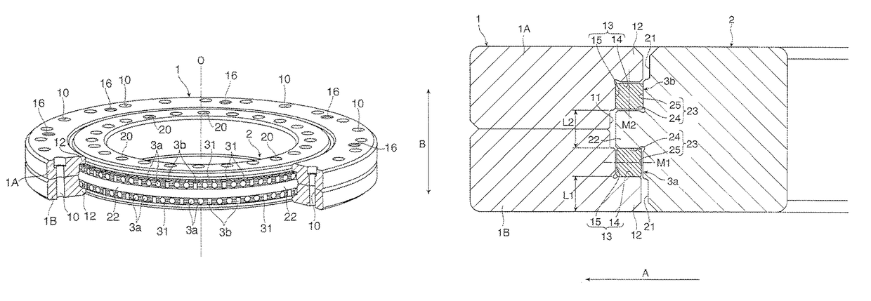
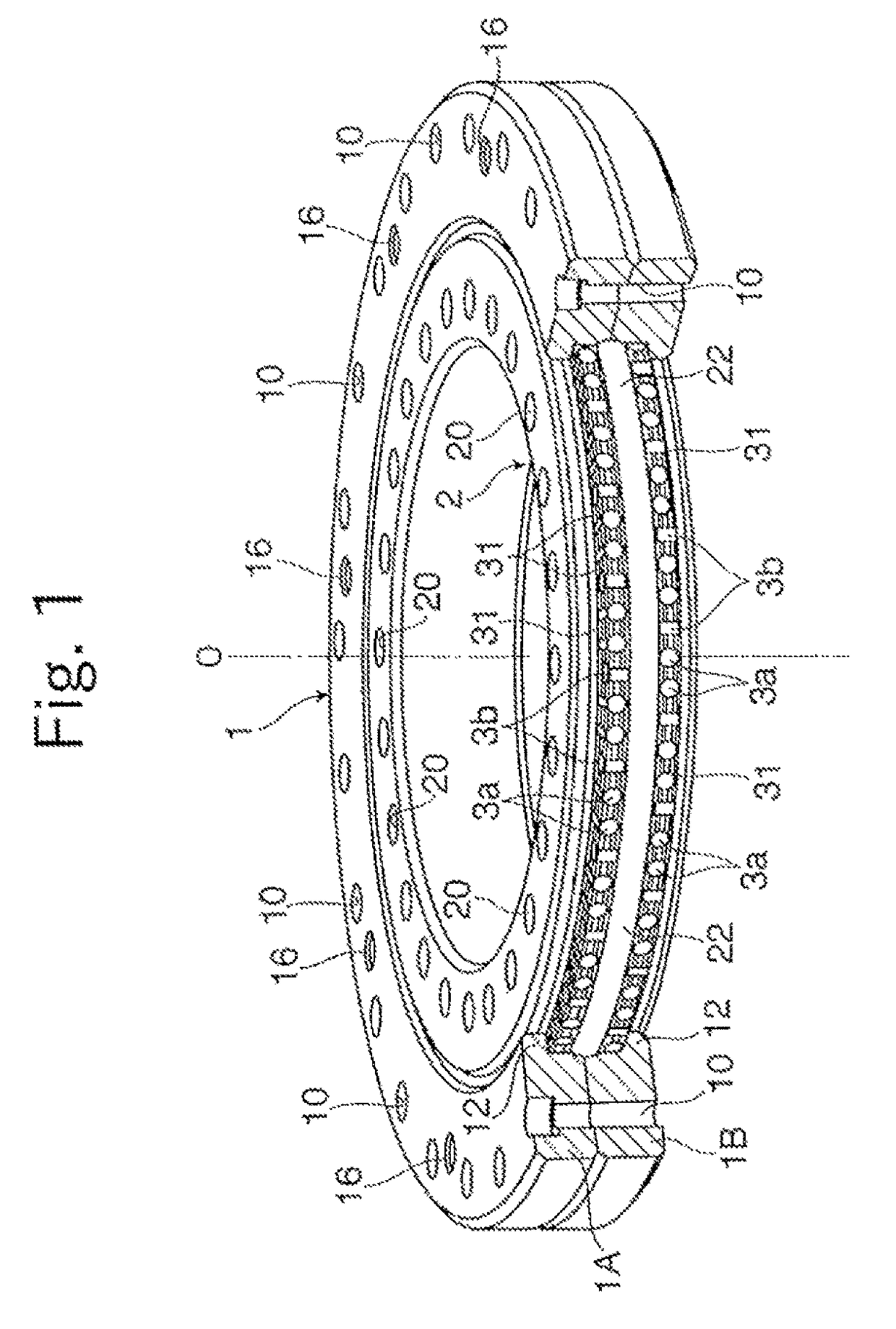
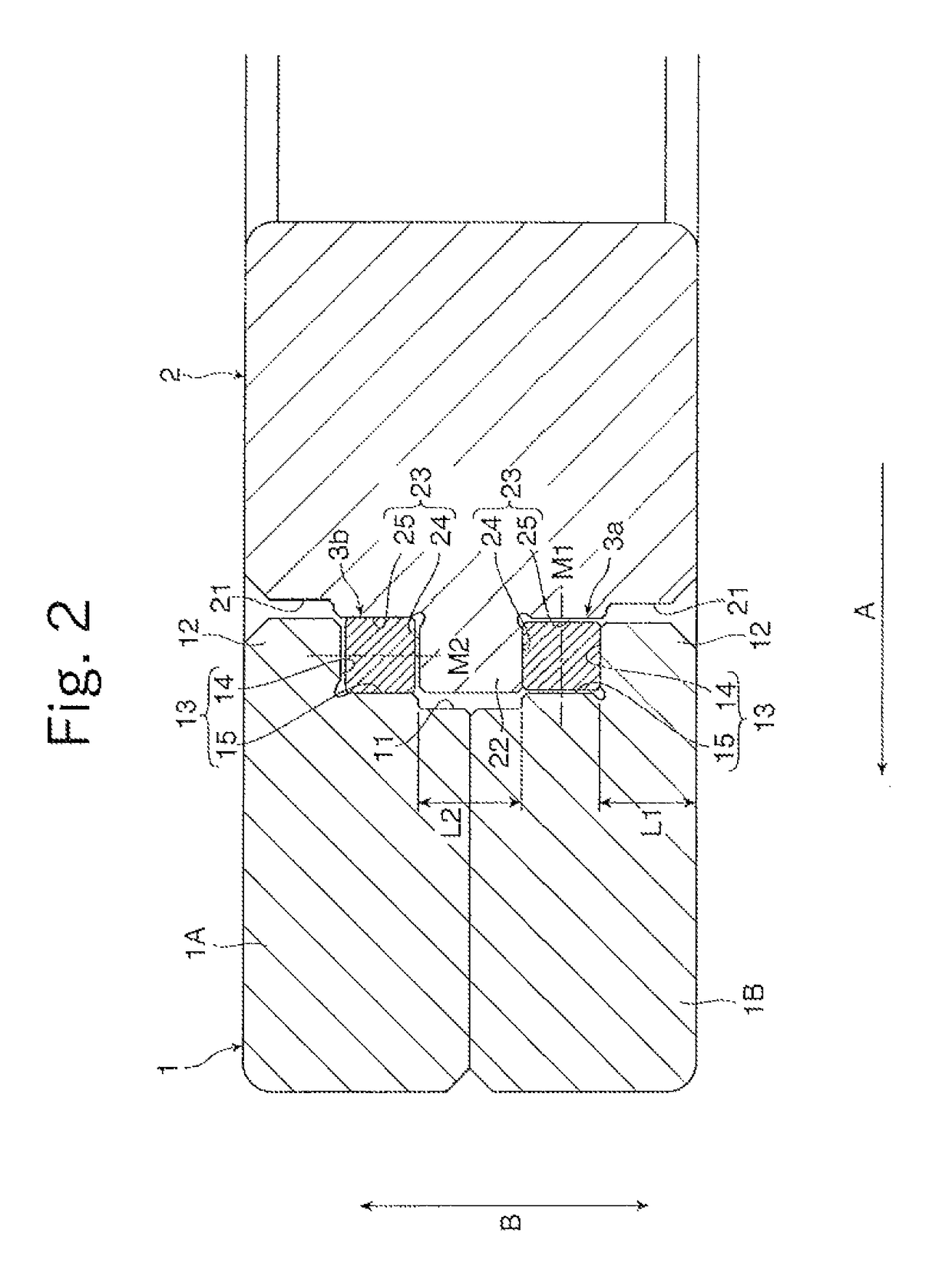
[0020]FIG. 1 and FIG. 2 are respectively a perspective view and a sectional view for illustrating a double-row roller bearing to which the present invention is applied. This double-row roller bearing includes an outer ring 1, an inner ring 2, and a large number of rollers 3 arrayed in two rows between the outer ring 1 and the inner ring 2, and the outer ring 1 and the inner ring 2 are combined with each other so as to be freely rotatable relative to each other along with rolling of the rollers 3. Note that, in FIG. 1, for the sake of better understanding of an internal structure of the double-row roller bearing, illustration of the outer ring 1 is partially cut out.

[0021]Bolt insertion holes 10 are formed through the outer ring 1 in a direction of a rotation axis O. The plurality of bolt insertion holes 10 are formed at equal intervals along a circumferential direction of the outer ring 1, and used at the time of fixing the outer ring 1 to a housing of, for example, a mechanical de...

second embodiment

[0051]Still further, also in the double-row roller bearing the first rollers 3a configured to bear the axial loads and the second rollers 3b configured to bear the radial loads are arranged in a mixed manner in each of the roller rolling passages 30. Specifically, the first rollers 3a bear only the axial loads between the first rolling surfaces 28a formed along the lateral protruding portions 27 of the inner ring 2 and the first rolling surfaces 18a formed along the intermediate protruding portion 17 of the outer ring 1. Meanwhile, the second rollers 3b bear only the radial loads between the second rolling surfaces 28b formed on the outer peripheral surface of the inner ring 2 and the second rolling surfaces 18b formed on the inner peripheral surface of the outer ring 1.

[0052]As described in the first embodiment, the double-row roller bearing of this type is used under the state in which any one of the outer ring 1 and the inner ring 2 is mounted to the stationary housing, and the ...

third embodiment

[0057]Further, in the double-row roller bearing each of the pair of the second rolling surfaces 28b of the inner ring 2 is formed on an outer peripheral surface of the main plate 2C. Thus, the pair of second rolling surfaces 28b can be machined at the same time on the main plate 2C. With this, the two inner raceway grooves 28 can be formed with high accuracy along the inner ring 2.

[0058]Further, bolt insertion holes 10a configured to allow the outer ring 1 to be fastened to the stationary housing are formed at equal intervals along the circumferential direction of the outer ring 1. The bolt insertion holes 10a each include a large diameter portion 10b configured to receive a head portion of the fixing bolt, and a small diameter portion 10c configured to allow a threaded portion of the fixing bolt to pass therethrough. An axial length of the large diameter portion 10b is set larger than an axial length of the small diameter portion. With this, the outer ring 1 can be suppressed from...


PUM

PropertyMeasurementUnit
angleaaaaaaaaaa
angleaaaaaaaaaa
thicknessaaaaaaaaaa

Abstract

Provided is a double-row roller bearing, which is capable of suppressing a frictional force from being increased due to variation in force of press contact between outer and inner rings and rollers to enable smoother relative rotational movement between the outer ring and the inner ring, and is also suitable for downsizing and higher in versatility.

Description

TECHNICAL FIELD[0001]The present invention relates to a double-row roller bearing to be used at a turning part of, for example, various machine tools, in which rolling passages for rollers are formed in double rows between an inner ring and an outer ring.BACKGROUND ART[0002]A roller bearing disclosed in Patent Literature 1 has been known as a roller bearing capable of bearing both axial loads applied in a direction parallel to a rotation axis of an inner ring and an outer ring, and radial loads applied in a direction orthogonal to the rotation axis. In this roller bearing, rolling passages for rollers are formed between the outer ring and the inner ring along a circumferential direction of the roller bearing, and the rollers are revolved while turning on their axes in the rolling passages along with relative rotational movement between the outer ring and the inner ring.[0003]Specifically, in the roller bearing illustrated in FIG. 5 of Patent Literature 1, two raceway grooves each ha...

Claims


Application Information

Patent Timeline
Patent Type & Authority Patents(United States)
IPC IPC(8): F16C33/58F16C19/38F16C33/60F16C33/78F16C33/66
CPCF16C33/585F16C19/38F16C33/60F16C33/6662F16C33/6685F16C33/7886F16C2240/46F16C2322/39
Inventor BAN, TOSHIKAZUMURATA, TOMOZUMIKOBAYASHI, HIROTAKE
Owner THK CO LTD
Why Eureka
Try Eureka