Signal transmission apparatus, distortion compensation apparatus, and signal transmission method

a distortion compensation and signal transmission technology, applied in the direction of digital transmission, amplifier modification to reduce non-linear distortion, baseband system details, etc., can solve the problems of limiting the modulation bandwidth of a transmission signal, limiting communication speed, and arithmetic circuit, so as to compensate for both in-band intermodulation distortion

Active Publication Date: 2017-03-14
NEC CORP
View PDF65 Cites 8 Cited by
  • Summary
  • Abstract
  • Description
  • Claims
  • Application Information

AI Technical Summary

Benefits of technology

[0020]The digital arithmetic circuit of Patent Document 1 can simultaneously compensate for in-band intermodulation distortion and cross-modulation distortion. However, the digital arithmetic circuit has a problem in that the modulation bandwidth of a transmission signal is restricted due to the operation speed of a central processing unit (CPU) or the operation speed of a digital-analog converter. The restriction of the modulation bandwidth of a transmission signal leads to the restriction of communication speed. In order to solve such a problem, it is preferable to perform implementation using the analog circuit rather than the digital arithmetic circuit.
[0022]An object of the present invention is to provide a signal transmission apparatus that compensates for both in-band intermodulation distortion and cross-modulation distortion occurring when signals of a plurality of bands are amplified by a single power amplifier, using an analog circuit.
[0023]According to the present invention, it is possible to compensate for in-band intermodulation distortion and cross-modulation distortion occurring when RF signals of a plurality of bands are collectively amplified by an amplifier, using an analog circuit.

Problems solved by technology

However, the digital arithmetic circuit has a problem in that the modulation bandwidth of a transmission signal is restricted due to the operation speed of a central processing unit (CPU) or the operation speed of a digital-analog converter.
The restriction of the modulation bandwidth of a transmission signal leads to the restriction of communication speed.
However, the analog circuit generally does not have flexible program functions.
For this reason, it is difficult to implement distortion compensation functions (functions of compensating for in-band intermodulation distortion and compensating for cross-modulation distortion simultaneously) of the above-mentioned digital arithmetic circuit onto one analog circuit.
Actually, the analog circuit disclosed in Patent Document 3 and the like compensates for only the in-band intermodulation distortion, and does not compensate for the cross-modulation distortion.

Method used


Image

  • Signal transmission apparatus, distortion compensation apparatus, and signal transmission method
  • Signal transmission apparatus, distortion compensation apparatus, and signal transmission method
  • Signal transmission apparatus, distortion compensation apparatus, and signal transmission method

Examples


first exemplary embodiment

[0041](First Exemplary Embodiment)

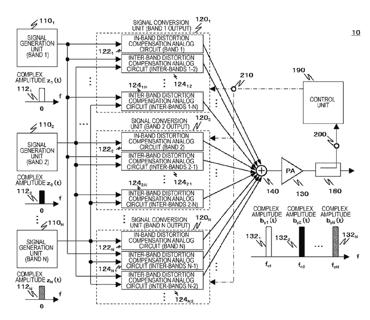
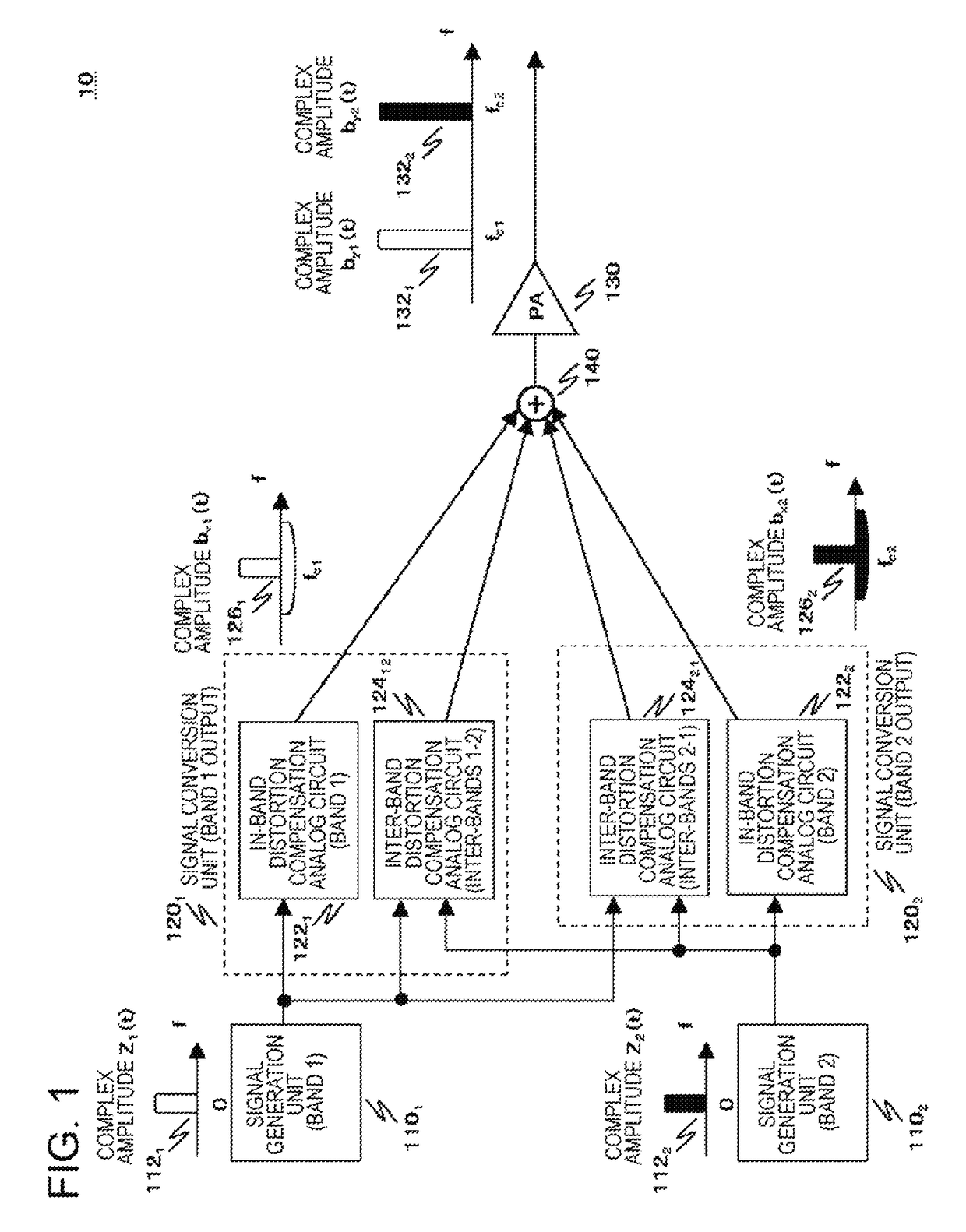
[0042]FIG. 1 is a block diagram illustrating a process configuration example of a signal transmission apparatus 10 in a first exemplary embodiment of the present invention. In FIG. 1, in order to simplify the description, an example is shown in which RF signals of 2 bands are simultaneously transmitted. Meanwhile, in the following description, when respective processing units included in the signal transmission apparatus 10 are required to be discriminated from each other for each band, a suffix indicating each band is given to the reference numerals and signs of the respective processing units.

[0043]The signal transmission apparatus 10 includes a signal generation unit 110, a signal conversion unit 120, and an amplification unit 130, and RF signals of a plurality of bands are simultaneously transmitted.

[0044]The signal generation unit 110 outputs a plurality of analog baseband signals corresponding to each band. In the example of FIG. 1, a signal g...

modification example

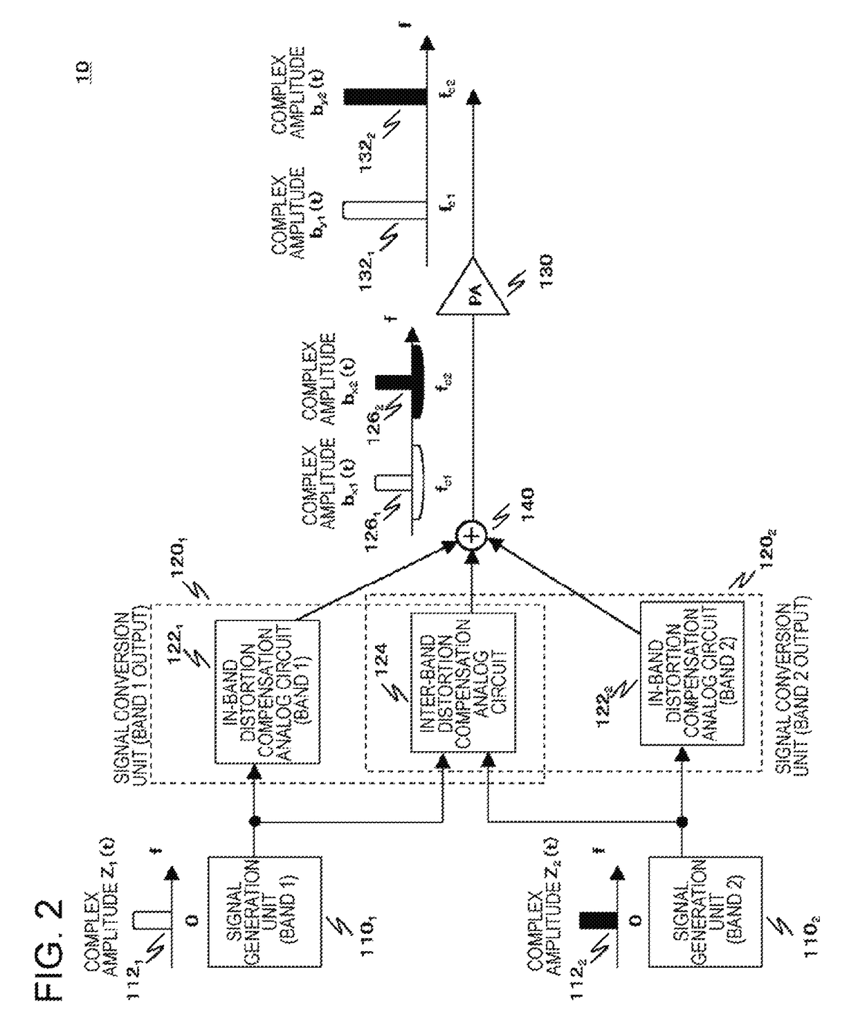
[0082](Modification Example of First Exemplary Embodiment)

[0083]FIG. 2 is a block diagram illustrating a process configuration example of a signal transmission apparatus 10 in a modification example of the first exemplary embodiment of the present invention. As shown in FIG. 2, the inter-band distortion compensation analog circuit 12412 and the inter-band distortion compensation analog circuit 12421 can also be integrated into an inter-band distortion compensation analog circuit 124 constituted by one circuit block.

[0084]The inter-band distortion compensation analog circuit 124 has a combined function of both the inter-band distortion compensation analog circuit 12412 and the inter-band distortion compensation analog circuit 12421. A plurality of analog baseband signals which are output from the signal generation unit 1101 and the signal generation unit 1102 are input to the inter-band distortion compensation analog circuit 124. Further, the inter-band distortion compensation analog...

second exemplary embodiment

[0087](Second Exemplary Embodiment)

[0088]FIG. 3 is a block diagram illustrating a process configuration example of a signal transmission apparatus 10 in a second exemplary embodiment of the present invention. FIG. 3 shows detailed configuration examples of the in-band distortion compensation analog circuit 1221 and the in-band distortion compensation analog circuit 1222, and those of the inter-band distortion compensation analog circuit 12412 and the inter-band distortion compensation analog circuit 12421.

[0089]In FIG. 3, double lines indicate two signal lines for transferring an in-phase component (I signal) and a quadrature component (Q signal) of a baseband signal. In addition, a normal solid line indicates one signal line for transferring a single baseband signal or an RF signal.

[0090]As shown in FIG. 3, the in-band distortion compensation analog circuit 1221 includes a square-law detector 12211, a multiplier 12221, baseband amplitude and phase correctors 12231 and 12241, an add...


PUM


Abstract

A signal conversion unit (120) of a signal transmission apparatus (10) includes an in-band distortion compensation analog circuit unit (122) that generates, for each band, an in-band distortion compensation signal for compensating for in-band intermodulation distortion occurring due to frequency mixing of RF signals of a single band, the distortion being included in RF signals which are output from an amplification unit (130), and causes the generated signal to be carried by the RF signals corresponding to the single band, and an inter-band distortion compensation analog circuit unit (124) that generates, for each combination of two bands, an inter-band distortion compensation signal for compensating for cross-modulation distortion occurring due to frequency mixing of RF signals between a plurality of bands which are input to the amplification unit (130), and causes the generated signal to be carried by each of the RF signals corresponding to the two bands.

Description

CROSS REFERENCE TO RELATED APPLICATIONS[0001]This application is a National Stage of International Application No. PCT / JP2014 / 072272filed Aug. 26, 2014, claiming priority based on Japanese Patent Application No. 2013-199295filed Sep. 26, 2013, the contents of all which are incorporated herein by reference in their entirety.TECHNICAL FIELD[0002]The present invention relates to a signal transmission apparatus that transmits radio frequency (RF) signals of a plurality of bands, a distortion compensation apparatus, and a signal transmission method.BACKGROUND ART[0003]Nonlinearity of a power amplifier (PA) in a radio transmission apparatus that amplifies an RF signal used in radio communication is a factor seriously distorting the RF signal. This distortion of the RF signal causes generation of power leakage to the outside of a desired band used in transmission. Therefore, suppressing the distortion of the RF signal to be transmitted becomes an important technical issue in the transmissi...

Claims


Application Information

Patent Timeline
Patent Type & Authority Patents(United States)
IPC IPC(8): H04K1/02H03F3/19H03F1/32H03F3/24H04L27/36H04L25/49H04L25/03H04B1/04
CPCH04L27/367H03F1/32H03F1/3247H03F3/19H03F3/24H04B1/04H04B1/0475H03F2200/451H03F2201/3215H04L25/03343
Inventor YAMANOUCHI, SHINGO
Owner NEC CORP
Why Eureka
Try Eureka