Wavelength converting member and projector including the wavelength converting member

a technology of converting member and wavelength, which is applied in the direction of picture reproducers using projection devices, lighting and heating apparatus, instruments, etc., can solve the problems of reducing the wavelength converting efficiency of phosphors, increasing manufacturing costs, and reducing the size of light source devices. achieve high converting efficiency and high converting efficiency

Active Publication Date: 2017-03-28
NICHIA CORP
View PDF18 Cites 1 Cited by
  • Summary
  • Abstract
  • Description
  • Claims
  • Application Information

AI Technical Summary

Benefits of technology

[0023]Accordingly, an object of the present invention is to improve disadvantages as described above, and to provide a wavelength converting member with high converting efficiency and a projector including the wavelength converting member.
[0025]According to the embodiments of the present invention, a wavelength converting member with high converting efficiency can be provided.
[0026]Further, according to the embodiments of the present invention, a projector using the wavelength converting member with high converting efficiency can be provided.

Problems solved by technology

However, in the light source device having such a phosphor wheel, an increase in the intensity of the light irradiated on the phosphors in order to achieve higher output increases the amount of heat generated by the phosphors that elevates the temperature of the phosphors, which may resulting in a reduction of the wavelength converting efficiency of the phosphors.
Accordingly, a reduction in size of the light source device becomes difficult.
Further, manufacturing costs also increase because of an increase in the number of components.
Still further, depending on the intended use, the simple cooling of the phosphor wheel fails to allow the phosphors to exhibit sufficient light emission efficiency.
Thus, in order to secure the sufficient amount of light, it may be difficult to reduce the size of the phosphor wheel (the wavelength converting member) and a projector.
Further, since the case storing the phosphor wheel and the air blower is required, a reduction in size of the light source device becomes difficult, and manufacturing costs also increase because of an increase in the number of components.
Still further, depending on the intended use, the simple cooling of the phosphor wheel fails to allow the phosphors to exhibit sufficient light emission efficiency.
Thus, in order to secure the sufficient amount of light, it may be difficult to reduce the size of the phosphor wheel (the wavelength converting member) and a projector.

Method used


Image

  • Wavelength converting member and projector including the wavelength converting member
  • Wavelength converting member and projector including the wavelength converting member
  • Wavelength converting member and projector including the wavelength converting member

Examples


Embodiment Construction

[0035]The wavelength converting member and the projector described below are to give a concrete form to technical ideas of the present invention, and the scope of the invention is not limited to those described below.

[0036]Further, the contents described in one embodiment can also be applied in other embodiments.

[0037]In the description below, when appropriate, terms which indicate specific directions or locations (for example, “up”, “down”, “right”, “left” and other terms expressing those) may be applied, but those terms are used for easy understanding of the disclosure with reference to the accompanying drawings, and thus the technical scope of the disclosure shall not be limited by the meaning of those terms.

[0038]As a result of thorough study, the inventors of the present invention have devised the following structure.

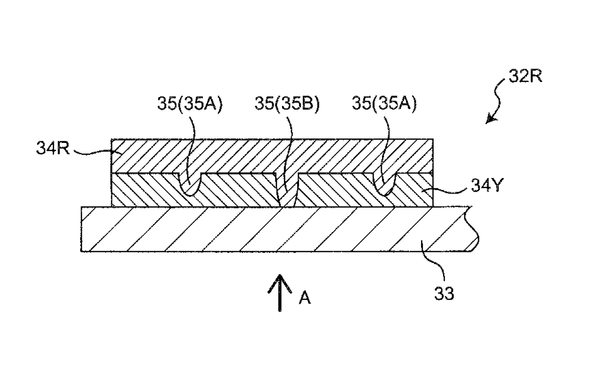
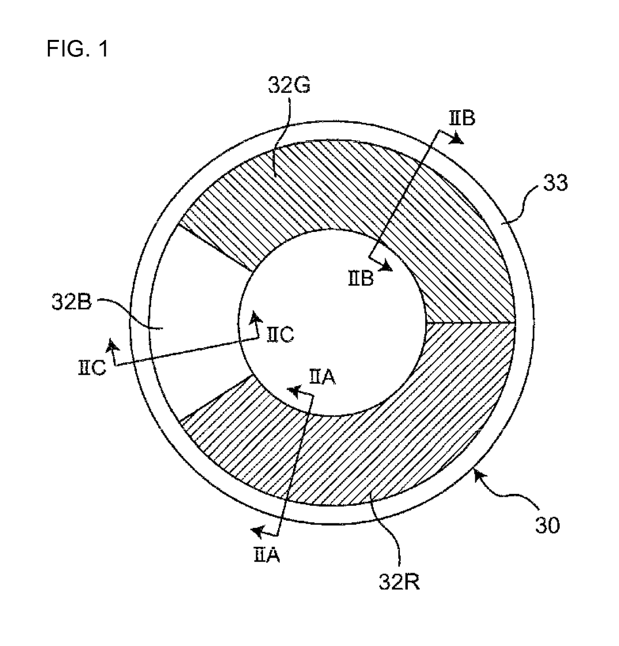
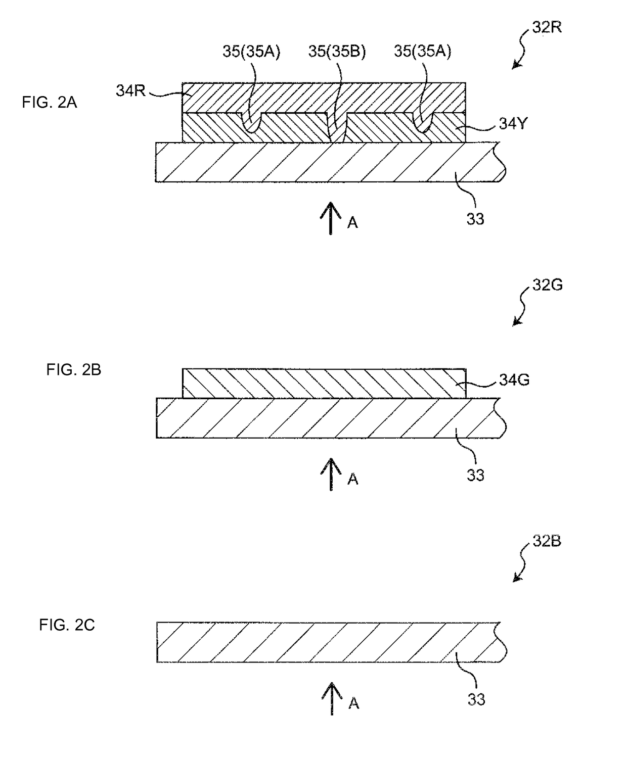
[0039]In at least one of wavelength converting regions (a first region) included in a phosphor wheel, in addition to a second phosphor layer containing a phosphor ...


PUM


Abstract

A wavelength converting member includes at least a first, second, and third regions, circumferentially on a disc-shaped light-transmissive substrate. The first region includes, from a light incident direction, a first and second phosphor layers. The first phosphor layer includes a first phosphor to absorb at least part of incident light and to emit a first light having a wavelength different from the incident light. The first phosphor layer defines an indentation in a surface on the second phosphor layer side, with a depth a half or more of the thickness of a portion of the first phosphor layer absent of the indentation. The second phosphor layer includes a second phosphor to absorb at least part of the first light emitted by the first phosphor and to emit a second light having a wavelength different from the first light, and is disposed in the indentation of the first phosphor layer.

Description

CROSS-REFERENCE TO RELATED APPLICATION[0001]This application claims priority to Japanese Patent Application No. 2014-236981 filed on Nov. 21, 2014. The entire disclosure of Japanese Patent Application No. 2014-236981 is hereby incorporated herein by reference.BACKGROUND[0002]1. Field[0003]Embodiments of the present invention relate to a wavelength converting member and a projector including the wavelength converting member.[0004]2. Description of Related Art[0005]In recent years, time-sharing type projectors have become popular, in which, light of a plurality of wavelengths is extracted in a time sharing manner, and the extracted light of a plurality of wavelengths is successively modulated to form and project an image.[0006]As a light source device for such a time sharing type projector, for example, there is a known light source device that includes a light source to emit a predetermined light such as a white light and a rotating wheel (i.e., wavelength converting member) having a...

Claims


Application Information

Patent Timeline
Patent Type & Authority Patents(United States)
IPC IPC(8): H04N9/31G02B27/14G02B26/00G03B21/20G03B33/08G03B21/00F21V9/40
CPCH04N9/3117G02B26/008G02B27/141G03B21/005G03B21/204G03B33/08H04N9/3114H04N9/3161
Inventor SAKA, NAOKIMURAZAKI, YOSHINORINIKI, ISAMU
Owner NICHIA CORP
Why Eureka
Try Eureka