Polarization conversion and recycling method and apparatus

Inactive Publication Date: 2006-08-29
MICROSENSOR TECH
View PDF8 Cites 2 Cited by
  • Summary
  • Abstract
  • Description
  • Claims
  • Application Information

AI Technical Summary

Benefits of technology

[0016]The primary objective of the present invention is to provide polarization rotation and converting devices and systems for rotating the direction of polarization of the incoming beam and efficiently converting the otherwise wasted polarizing beam from a light source into the wanted polarization.
[0019]It is yet another objective of the present invention to provide a reflector apparatus for polarization rotation, which is not sensitive to polarization alignment errors.
[0023]Several preferred sample embodiments are disclosed by integrating or combining said apparatus into different optical arrangements, each configuration comprising one or more said apparatus of half-pyramid shaped reflector, such as, said reflector with triangular entrance / exit surface, an assembly of two said reflectors with square entrance / exit surface, a strip of said reflectors, and an array of said reflectors. The disclosed polarization converting system has the advantage of high converting efficiency, stability at high light flux and tolerance to high temperature. Other advantages of the disclosed system, resulting from no waveplate employed in the disclosed system, include its insensitivity to wavelength variations of the light source, to temperature changes, and to polarization alignment errors.
[0024]In addition, for its simplicity in structure and ease in fabrication, the invented apparatus of half-pyramid shaped reflector and derived polarizing converter systems have substantial benefits over waveplate-dependent polarization conversion systems and are potentially useful in many polarization conversion applications. A typical application of this invention is to provide a polarized light source with improved efficiency for the projection systems utilizing polarization dependent spatial light modulation panels, either transmissive or reflective, such as LCD (Liquid Crystal Display) and LCOS (Liquid Crystal On Silicon). By further customizing and configuring the disclosed apparatuses, the disclosed method can encompass more embodiments and be adopted into more polarization converting systems, including the polarization systems where no polarization recovering device exists previously, and polarization conversion systems where the waveplate works as the key polarization converting and recycling component.

Problems solved by technology

It is evident that conventional reflective polarizers with no polarization conversion and recycling device attached are inefficient, due to the fact that, during s-p polarization split, severe loss of light occurs and only a maximum of one-half of the available light from the source can be converted to polarized light for transmission.
However, the methodology of employing waveplates in a polarization converter inevitably leads to some problems.
One of the disadvantages is that the waveplates will not work properly if the wavelengths of the illumination beam deviate considerably from the center wavelength.
Another disadvantage is that the waveplates are sensitive to changes of the incident angles and the direction of polarization.
Furthermore, a waveplate made of polymer is thermally unstable, while although a waveplate made of crystal can tolerate high temperature and rapid temperature change, its cost is usually too high.
These issues have restricted the use of waveplate in some practical applications, particularly in those applications where working with a high flux of broadband light and / or a high operation temperature is unavoidable.
These findings and derived systems are often too complicated to be used in practical polarization applications.
However, the disclosed prism polarizer is not very suitable for many applications due to its triangular shaped incident surface.
Due to its potential complexity, again, this configuration is not very practically useful for many real applications.

Method used


Image

  • Polarization conversion and recycling method and apparatus
  • Polarization conversion and recycling method and apparatus
  • Polarization conversion and recycling method and apparatus

Examples


Embodiment Construction

[0041]The present invention is further described based on several sample embodiments, but embodiments of this invention are not limited to these examples. All embodiments demonstrate the usefulness of the invention and its versatility in a variety of polarization rotating, converting, and recycling applications.

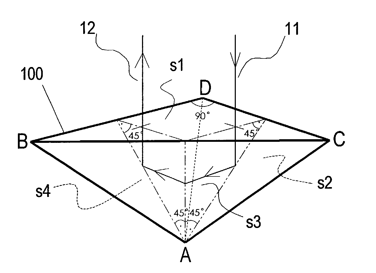
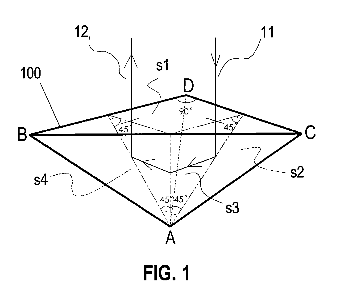
[0042]FIG. 1 is a conceptual construction view showing a model of HP reflector, which comprises four triangular surfaces with four vertexes A, C, B, and D, wherein the surface s1 (BCD), in the shape of an isosceles right triangle, denotes the incident light entrance surface and light exit surface; the surface s2 (CDA), surface s3 (BAC) and surface s4 (DBA) denote three reflecting surfaces adjacent to each other. The reflecting surface s3 is perpendicular to the entrance / exit surface s1. The other two reflecting surfaces, surface s2 and surface s4, are both at a 45 degrees angle with respect to surface s1 to form a half-pyramid shaped reflector.

[0043]To illustrate the basic pr...


PUM


Abstract

A method, apparatus and system for polarization conversion and recycling by using a half-pyramid shaped reflector with multiple reflective surfaces, or said reflector assembly, to obtain a desirable polarization rotation effect. The disclosed half-pyramid reflector comprises a plurality of reflective surfaces, which are formed so that an incoming beam passing perpendicularly through the entrant surface is reflected three times inside the device and leaves the exit surface with the direction of polarization being rotated 90 degrees. The preferred embodiments of polarization:conversion systems using the invented apparatus are included. Without employing any waveplate component, the disclosed system is not sensitive to wavelength variations of the light source, temperature changes, and polarization alignment errors. Typical application of this invention includes polarization conversion and recycling for projection systems with polarization dependent spatial light modulation panels, such as LCD (Liquid Crystal Display) and LCOS (Liquid Crystal On Silicon).

Description

CROSS REFERENCE TO RELATED APPLICATIONS[0001]This application is in-part a continuation of the U.S. provisional Patent Application Ser. No. 60 / 424,171 filed Nov. 7, 2002, entitled “Polarization conversion and recycling method and apparatus”.BACKGROUND OF INVENTION[0002]1. Field of the Invention[0003]The present invention relates generally to a polarization conversion and recycling method that features a polarization converting apparatus using a uniquely designed half-pyramid shaped reflector with multi-reflection to achieve a desirable polarization rotation function. The present invention further relates to polarization conversion and recycling systems using the same.[0004]2. Description of the Prior Art[0005]Polarized light sources are utilized in various applications such as LCD (Liquid Crystal Display) and LCOS (Liquid Crystal On Silicon) projection systems. Un-polarized light source can be decomposed by a polarizing beam splitter (PBS) into a linear s-polarization component and ...

Claims


Application Information

Patent Timeline
IPC IPC(8): F21V5/02F21V7/04G02B27/28H04N5/74
CPCH04N5/7416G02B27/286
Inventor LI, HAIZHANGGUO, BUJINLI, XIAODAN
Owner MICROSENSOR TECH
Why Eureka
Try Eureka