Modular panel units for constructional purposes

a technology of modular panels and construction, applied in the direction of roofs, coverings/linings, building components, etc., can solve the problems of causing problems such as difficulty in waterproofing and enduring strong winds

Active Publication Date: 2012-11-27
DAN PAL
View PDF34 Cites 35 Cited by
  • Summary
  • Abstract
  • Description
  • Claims
  • Application Information

AI Technical Summary

Benefits of technology

[0005]It is therefore a broad object of the present invention to ameliorate the disadvantages of the above-described panel units and to provide panel units rendering the construction sturdier to weather conditions.

Problems solved by technology

While such panels have been used to advantage for many years, it has been found that in some instances under adverse weather conditions, difficulties may be created with respect to waterproofing and withstanding strong winds, especially with a structure composed of two parallel disposed panel units interconnected by H-shaped connectors.

Method used


Image

  • Modular panel units for constructional purposes
  • Modular panel units for constructional purposes
  • Modular panel units for constructional purposes

Examples


Embodiment Construction

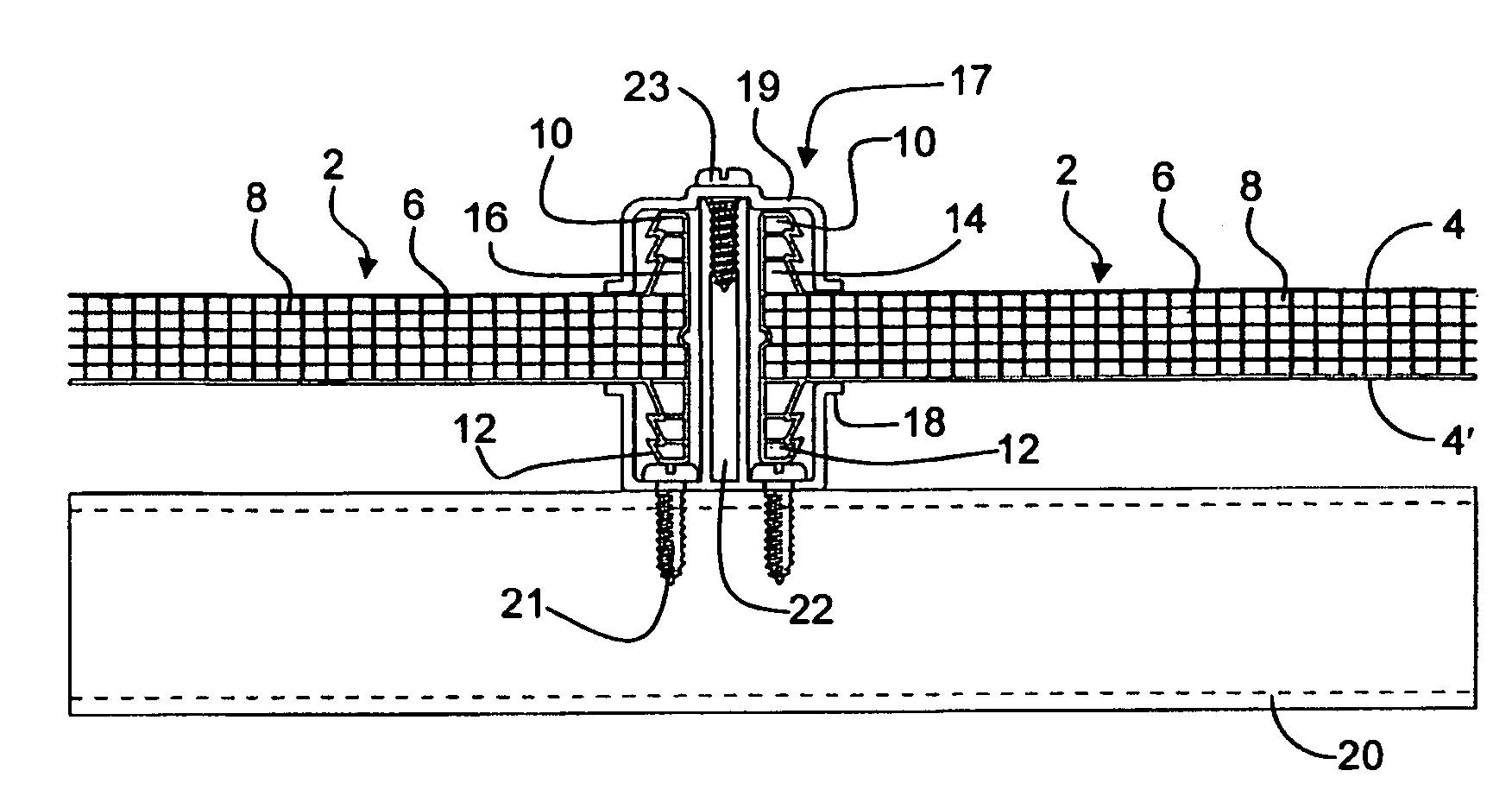
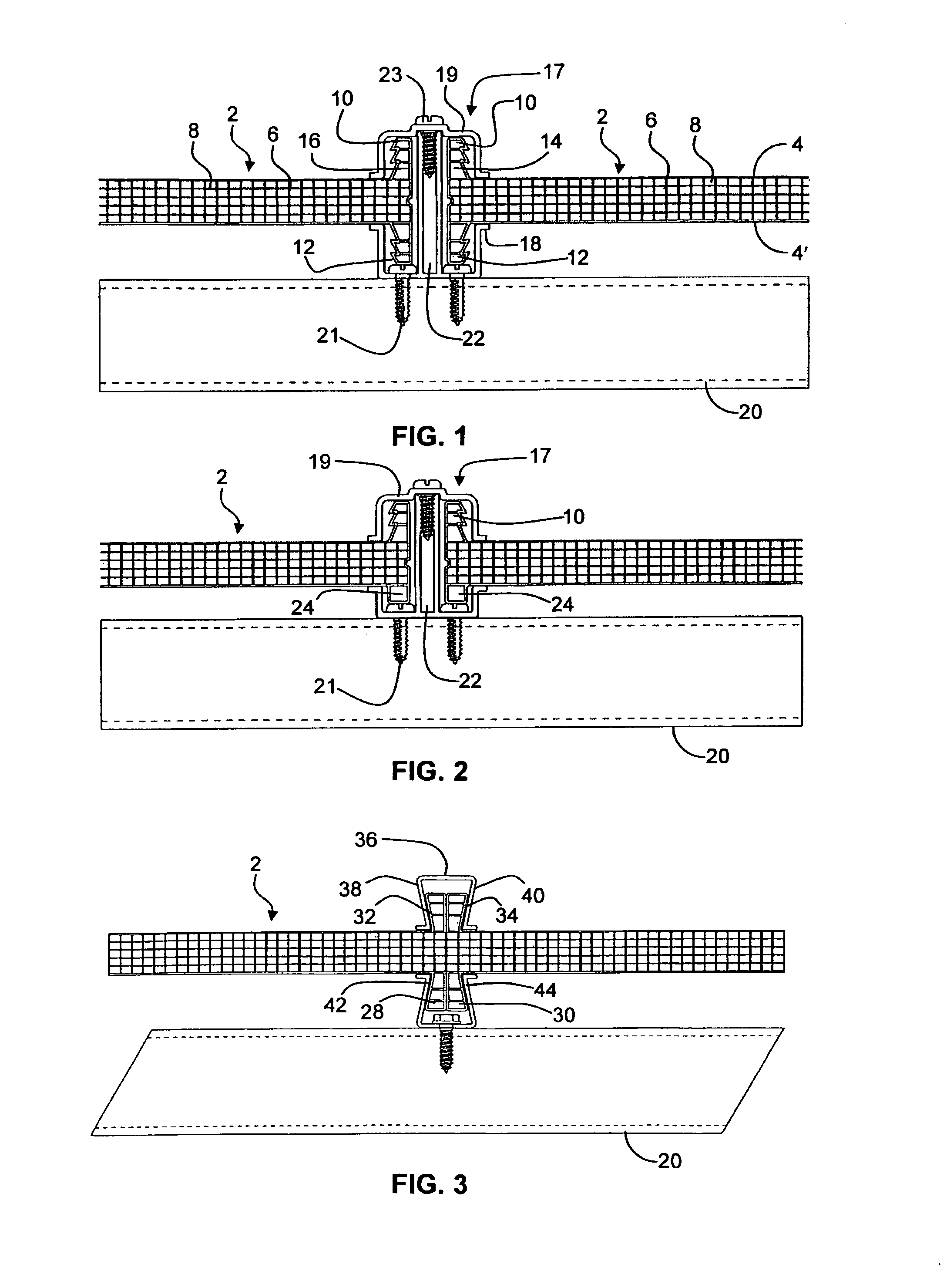
[0016]FIG. 1 shows two juxtaposed and interconnected panel units 2 for constructional purposes, according to an embodiment of the invention. Typically, such panel units are manufactured by extrusion. Each of the panel units includes two major surfaces 4, 4′, interconnected by a plurality of ribs 6 and / or intermediate surfaces 8, dividing the space defined between the major surfaces into a plurality of sub-spaces. Each of the panel units has at least two joining flanges 10, 12, located at, or adjacent to, a common edge of the respective panel unit 2. Each of the flanges 10, 12 in the respective panel unit projects from a different major surface 4 or 4′ of the panel unit 2. Although not shown in the figure, typically one of the two flanges projects from one major surface and two flanges project from the other major surface. The flanges may project from the major surfaces at right angles, or at a non-normal angle thereto; they may be aligned with another flange at the same edge of the ...


PUM


Abstract

A panel unit (2) for constructional purposes has at least two joining flanges (10, 12) on opposite surfaces (4, 4′) located at, or adjacent to, a common edge of the panel unit, and projecting in mutually opposite directions. Two such panel units (2) may be juxtaposed end to end and secured by a two-part connector (17) having a base portion (18) that is adapted for attaching to a fixed structural element (20) and for anchoring to the flanges (12) on a first surface (4′) of the panel units 2, and a cap (19) adapted for anchoring to the flanges (10) on an opposite surface (4) of the panel units (2) and for anchoring to the base portion.

Description

FIELD OF THE INVENTION[0001]The present invention relates to modular panel units for the construction of walls, ceilings, roofs, canopies and windows, particularly of light-transmitting wall sections. More specifically, the present invention relates to such panel units having joining-flanges at their ends and being manufactured by extrusion.BACKGROUND OF THE INVENTION[0002]Extruded modular panel units of the type of the present invention are known, for example, from the U.S. Pat. Nos. 4,573,300, 4,998,395 and 5,348,790, the teachings of which are incorporated herein by reference.[0003]In all of these patents, there are disclosed panel units having two interconnected, spaced-apart major surfaces and a joining flange at each of its ends, both flanges projecting at the same direction from a single major surface of the panel.[0004]While such panels have been used to advantage for many years, it has been found that in some instances under adverse weather conditions, difficulties may be c...

Claims


Application Information

Patent Timeline
Patent Type & Authority Patents(United States)
IPC IPC(8): E04H9/16E04H9/14
CPCE04C2/543E04D3/28E04D2003/285E04C2/54E04D3/36E04F13/26
Inventor BEN-ZVI, NIR
Owner DAN PAL
Why Eureka
Try Eureka