Method for constructing a chair-type, self-supported earth retaining wall

a self-supporting, earth-supported technology, applied in the direction of artificial islands, excavations, constructions, etc., can solve the problems of durability and waterproof properties of the completed underground structure, large quantity of steel sheets, and large construction costs, so as to save construction costs, shorten construction period, and reduce the quantity of steel sheets used

a self-supporting, earth-supported technology, applied in the direction of artificial islands, excavations, constructions, etc., can solve the problems of durability and waterproof properties of the completed underground structure, large quantity of steel sheets, and large construction costs, so as to save construction costs, shorten construction period, and reduce the quantity of steel sheets used

US20110142550A1Inactive Publication Date: 2011-06-16KOLON CONSTR CO LTD

Image

  • Method for constructing a chair-type, self-supported earth retaining wall
  • Method for constructing a chair-type, self-supported earth retaining wall
  • Method for constructing a chair-type, self-supported earth retaining wall

Examples


Embodiment Construction

[0034]Now, preferred embodiments of the present invention will be described hereinafter in detail with reference to FIGS. 1 to 9.

[0035]In the meantime, the illustration and detailed description of the constitution, operation, and effects that can be easily understood from a general earth retaining construction technique and a related technique applied to the present invention in the drawings will be omitted or only portions related with the present invention will be shown and described.

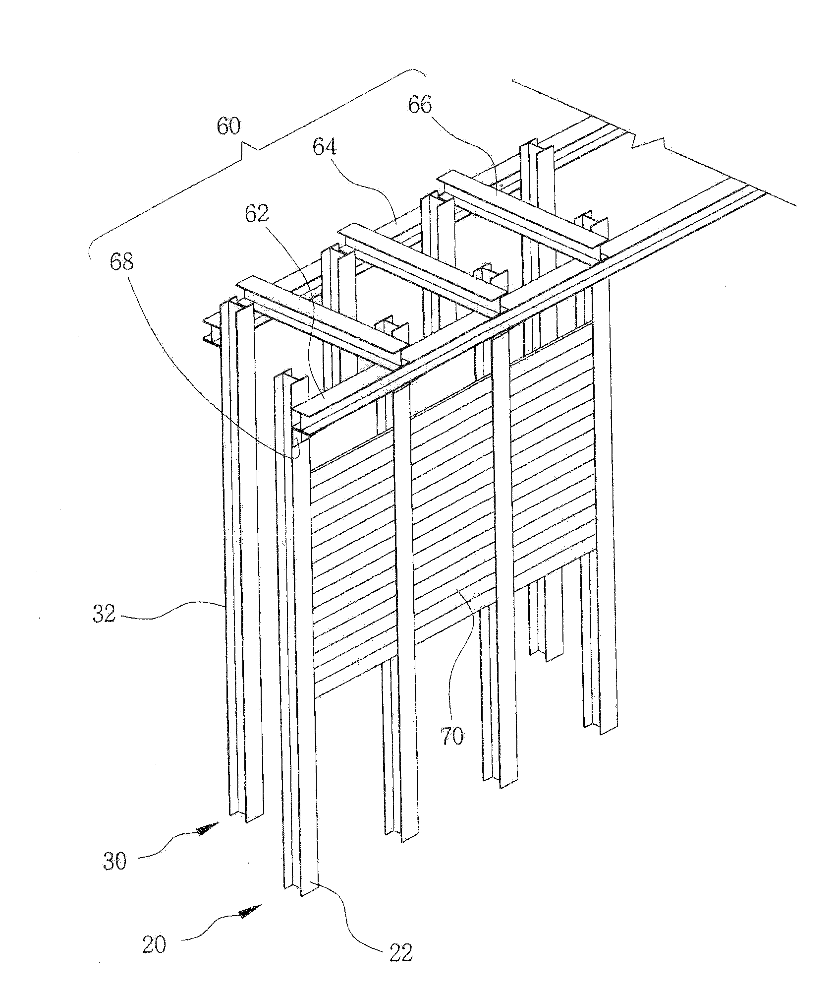
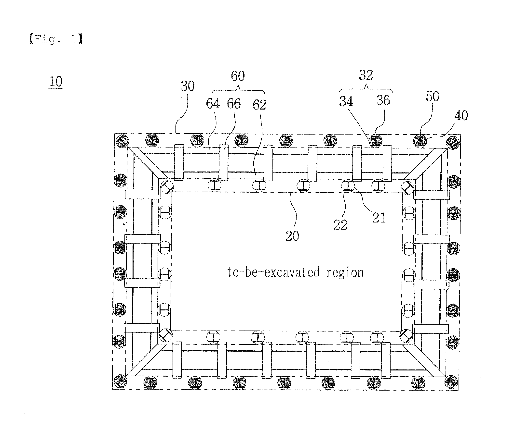
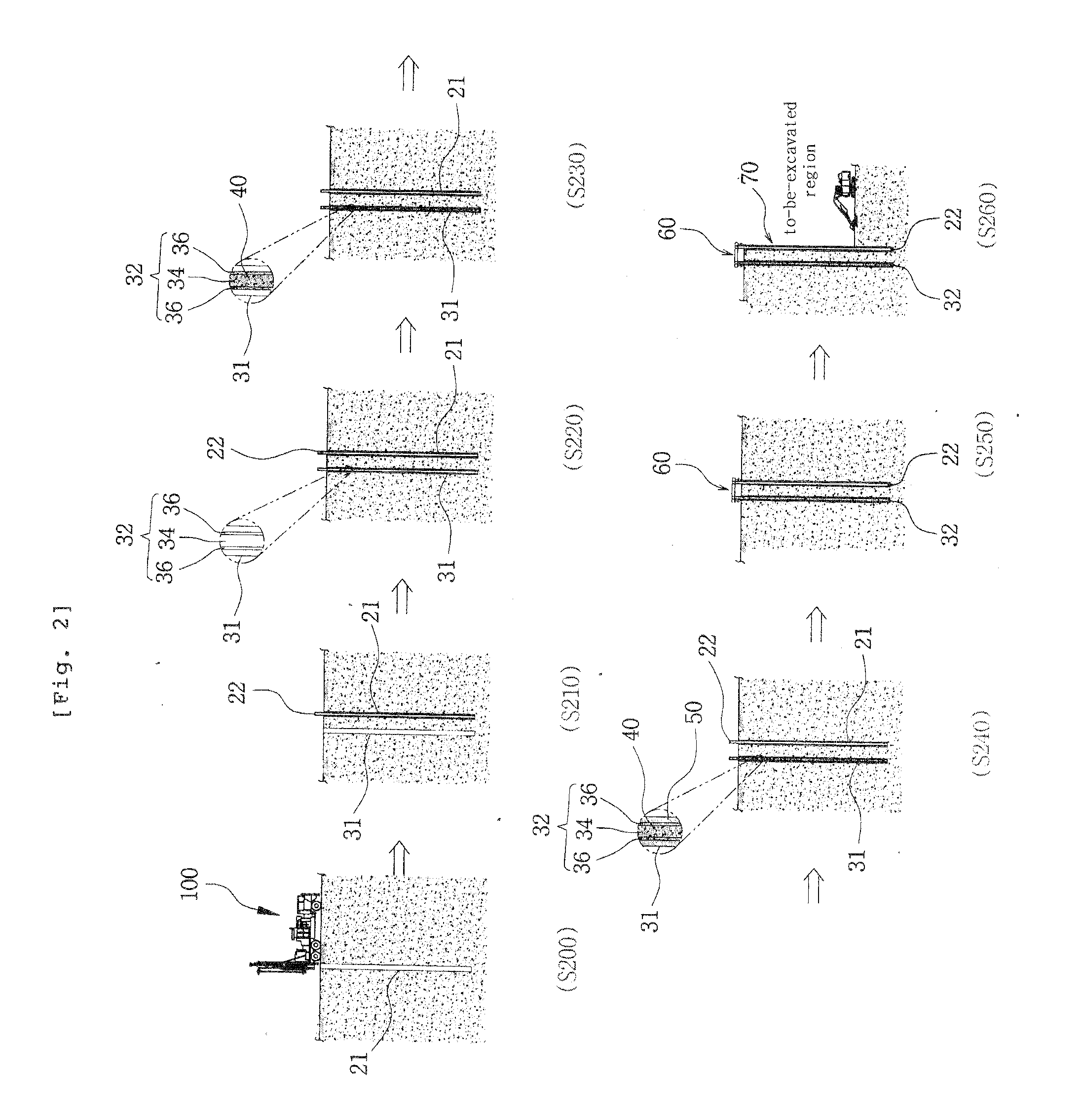
[0036]FIG. 1 is a schematic top plan view illustrating an earth retaining wall constructed by a method for constructing a chair-type, self-supported earth retaining wall according to the present invention, FIG. 2 is a view for explaining a method for constructing a chair-type, self-supported earth retaining wall according to a preferred embodiment of the present invention, FIG. 3 is a perspective view illustrating a constitution of an earth retaining wall constructed by the method for constructing the...


PUM


Abstract

The present invention provides a method for constructing a chair-type, self-supported earth retaining wall used for retaining external forces such as earth pressure prior to an excavation. The method of the present invention forms a first column of piles having a plurality of piles arranged along the circumference of the region to be excavated. Subsequently, the method comprises forming a second column of piles having a plurality of piles by consecutively perforating a plurality of holes by a predetermined spacing at predetermined positions outwardly from the first column of piles, along the circumference of the region to be excavated, inserting H-beams into the respective holes, filling left and right spaces of the webs of the H-beams with soil, and filling the outer spaces of the flanges of the H-beams with a flowable stiffening material. The method subsequently comprises interconnecting the first column of piles and the second column of piles by a connection member. The first column of piles and the second column of piles are formed along the circumference of the region to be excavated, with an outward spacing, and connected to each other by the connection member.The present invention provides a method for constructing a chair-type, self-supported earth retaining wall used for supporting external forces such as earth pressure prior to an excavation. The method of the present invention comprises forming a first pile array 20 having a plurality of piles 22 arranged along a circumference of an region to be excavated. Subsequently, the method comprises forming a second pile array 30 having a plurality of piles arranged along a circumference of the to-be-excavated region by consecutively drilling a plurality of boreholes 31 at predetermined intervals at predetermined positions outwardly spaced apart from the first pile array, inserting H-beams into the respective boreholes, filling left and right spaces of webs 34 of the H-beams 32 with soil 40, and filling the outer spaces of flanges 36 of the H-beams with a flowable hardening material 50. The method subsequently comprises fixedly interconnecting the first pile array and the second pile array using a connection member. The first pile array and the second pile array are formed in such a fashion as to be outwardly spaced apart from each other along the circumferences of the to-be-excavated region, and are connected to each other by the connection member to construct an underground earth retaining wall.

Description

TECHNICAL FIELD[0001]The present invention relate to a method for constructing a chair-type, self-supported earth retaining wall, and particularly to, such a method for constructing a chair-type, self-supported earth retaining wall, in which an earth retaining wall used for supporting an external force such as earth pressure or the like prior to an excavation can be constructed by a supporting construction technique employing an improved double-row pile structure so as to complement various shortcomings involved in a conventional temporary facility construction technique such as a strut supporting construction technique, an earth anchor construction technique or the like.BACKGROUND ART[0002]In general, when filling the ground, cutting the ground, or drilling the ground, and the like are performed, while a slope surface is generally formed to maintain the stability of the ground. However, when the excavation is performed to improve the utility of the land more effectively or to impro...

Claims


Application Information

Patent Timeline
16 Jun 2011
Publication
US20110142550A1
IPC
E02D17/00
CPC
E02D17/04; E02D5/18; E02D17/08; E02D2220/00; E02D2600/20
Inventors
LEE, JAE HO