Ligament reconstruction fixation system

a fixation system and ligament technology, applied in the field of tissue surgical repair, can solve the problems of inefficiency of surgical procedures used with these devices, and do not allow optimal contact of graft tissue or scaffold with the bone, and achieve the effect of promoting faster healing

Inactive Publication Date: 2017-04-25
SMITH & NEPHEW INC
View PDF9 Cites 0 Cited by
  • Summary
  • Abstract
  • Description
  • Claims
  • Application Information

AI Technical Summary

Benefits of technology

[0004]In one aspect, the present disclosure relates to an assembly for fixing a ligament in bone. The assembly includes a suspension member having a first end for receiving a bone graft, and an implant having a mechanism for fixedly receiving a second end of the suspension member and at least partially suspending the suspension member within the implant, allowing for bony in-growth. Such an assembly allows a tissue graft to be suspended within a bone tunnel and eventually to contact the bone tunnel walls through a full 360 degrees which promotes faster healing. In a further embodiment, implant is a fenestrated implant, and the second end of the suspension member includes a suture loop hook having at least two hook portions, and the mechanism for fixedly receiving the second end of the suspension member includes apertures in the fenestrated implant. In another embodiment, fenestrated implant is a Healicoil suture anchor. In yet another embodiment, the assembly further includes a guide pin having an attachment site for the suspension member and wherein the guide pin is threaded through the implant. In a further embodiment, the implant is a bioabsorbable material.
[0007]In a further embodiment, implant fixation and graft to socket contact are maximized by sizing the implant proportionally to a size of the graft and a size of the pilot hole. In another embodiment, engaging the suspension member with the implant includes hooking at least two hooks portions disposed on the second end of the suspension member to apertures in the fenestrated implant. In a further embodiment, engaging the suspension member with the implant includes locking at least two suspension member J-lock members into corresponding J-lock retainer grooves in the implant.

Problems solved by technology

Some of the surgical procedures used with these devices are inefficient and some of the devices do not allow optimal contact of the graft tissue or scaffold with the bone.

Method used


Image

  • Ligament reconstruction fixation system
  • Ligament reconstruction fixation system
  • Ligament reconstruction fixation system

Examples


Embodiment Construction

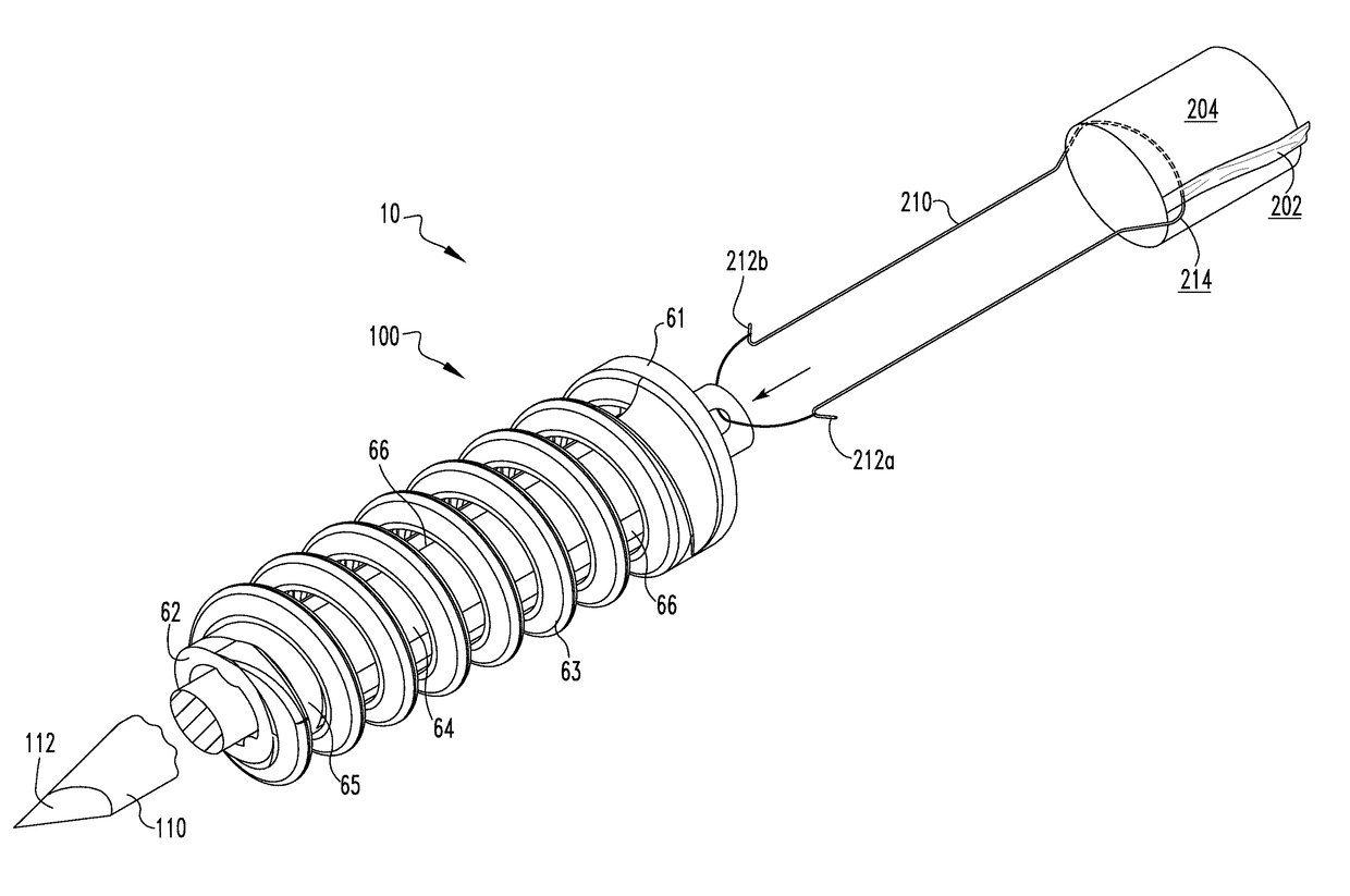
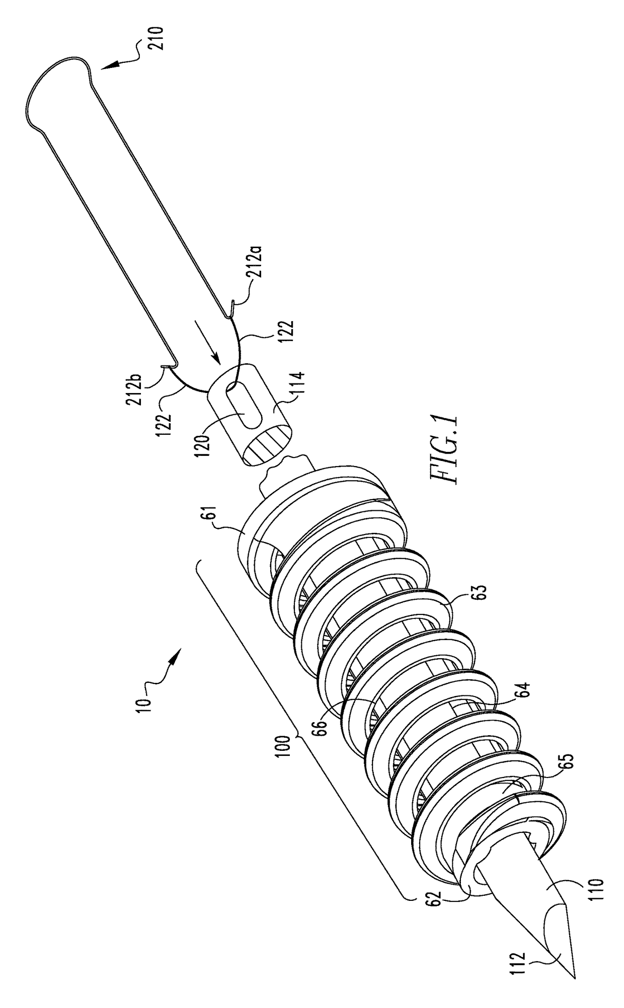
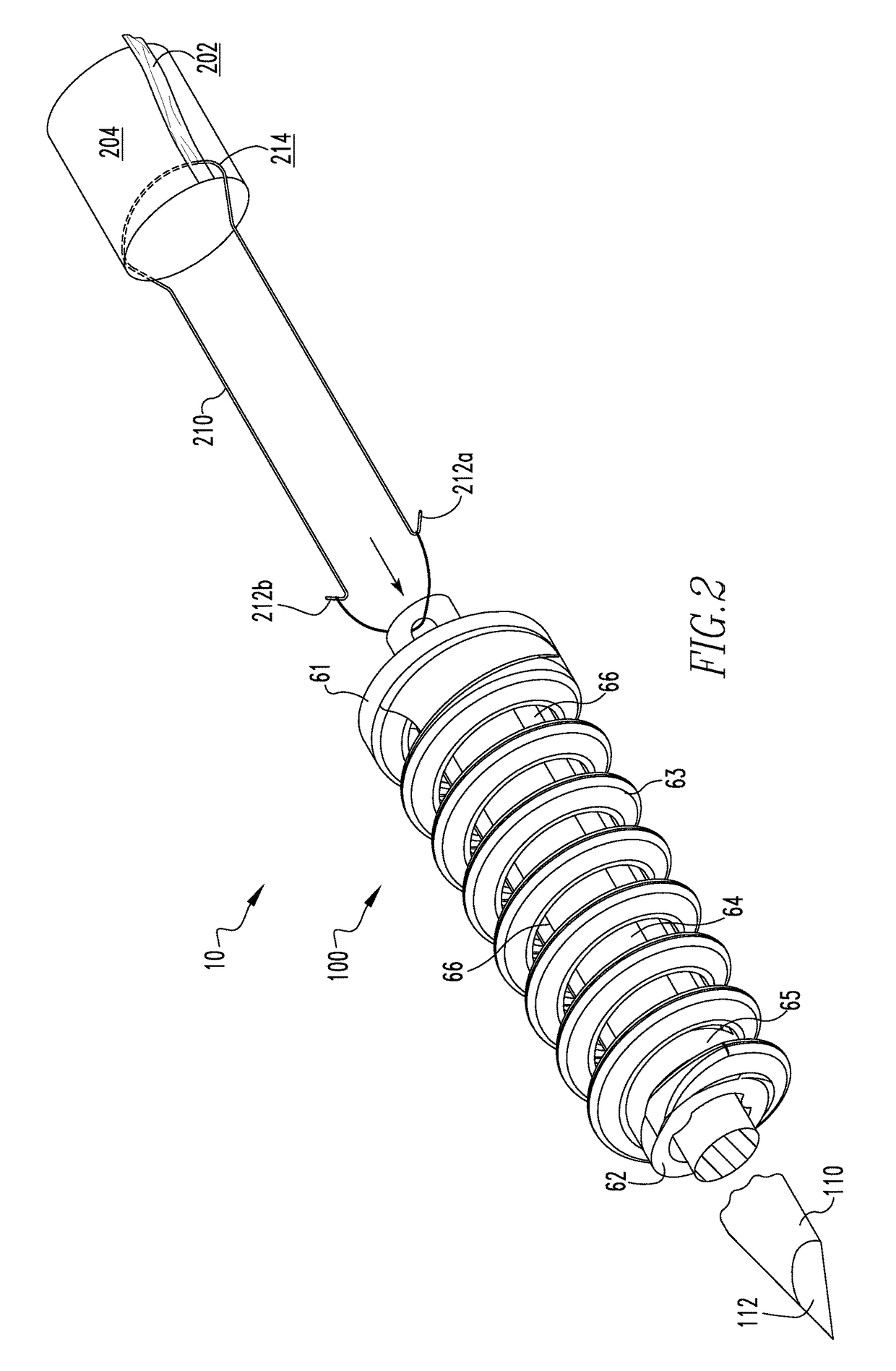
[0014]The following description of the preferred embodiment(s) is merely exemplary in nature and is in no way intended to limit the disclosure, its application, or uses. As disclosed herein, an assembly for fixing a ligament in bone includes an implant and matching suspension member which is attached to the implant during ligament reconstruction procedures. This assembly suspends a bone graft connected to the suspension member distally from the implant which may be attached to a drill via a guide pin and inserted during pilot hole placement.

[0015]Now referring to FIG. 1, an exemplary assembly 10 for fixing a ligament in bone includes an implant 100 which is inserted, for example, in a bone tunnel in a femoral socket. The implant 100 includes a distal end 61, a proximal end 62, a coil portion 63 (also referred to as a thread) and apertures 64-66. In one embodiment, prior to insertion, the implant is assembled on a drill guide wire 110 (also referred to as a guide pin 110). The drill ...


PUM


Abstract

The present disclosure relates to an assembly for fixing a ligament in bone. The assembly includes a suspension member and an implant having a mechanism for fixedly receiving the suspension member and at least partially suspending the suspension member and the received bone graft within the implant, allowing for bony in-growth. A method of fixing a ligament in bone is also disclosed.

Description

FIELD OF TECHNOLOGY[0001]The present disclosure relates to the surgical repair of tissue and, more specifically, devices and methods for ligament reconstruction.RELATED ART[0002]Fibrous tissues, such as ligaments and tendons, can detach from bone. Suture anchors are commonly used to attach soft and hard tissue to bone. Typically, a suture anchor is implanted into a drilled bore in bone mass. One or more sutures with attached needles are connected to the suture anchor. The suture is passed through the tissue and subsequently tied to secure the tissue to the bone.[0003]Many ligament reconstruction fixation devices such as endobutton or suspension pins have been identified as potential solutions to fix ligaments during surgical reconstruction. Some of the surgical procedures used with these devices are inefficient and some of the devices do not allow optimal contact of the graft tissue or scaffold with the bone.SUMMARY OF THE INVENTION[0004]In one aspect, the present disclosure relates...

Claims


Application Information

Patent Timeline
Patent Type & Authority Patents(United States)
IPC IPC(8): A61F2/08A61B17/04
CPCA61F2/0811A61B17/0401A61F2002/0882A61B2017/044A61B2017/0414A61B2017/0445A61F2002/087A61F2002/0817A61F2002/0829A61F2002/0841A61F2002/0847A61F2002/0852A61F2002/0858A61B2017/0464
Inventor SHINO, KONSEISANTANGELO, STEPHENWYMAN, JEFFREY
Owner SMITH & NEPHEW INC
Why Eureka
Try Eureka