Pain relief device

a pain relief device and electric stimulation technology, applied in the field of pain relief devices, can solve the problems of nothing stopping the appositely charged particles from passing through, and achieve the effects of reducing pain, promoting faster healing of joints or muscles, and maximizing the effect of conducting pads

Inactive Publication Date: 2010-12-28
POLLOCK FREDERICK WILLIAM
View PDF24 Cites 2 Cited by
  • Summary
  • Abstract
  • Description
  • Claims
  • Application Information

AI Technical Summary

Benefits of technology

[0006]When these two pads, wired as above, are placed on the body simultaneously, an electric field is set up flowing through the body from the positively (+) charged pad to the negatively (−) charged pad. At the location of the insulated pad, no current can flow from the body to the negative (−) electrode within as it is completely electrically insulated. The negative (−) electric field created by the electrode will still, however, flow through the insulation and flow throughout the body. When the positively (+) charged conducting pad is placed on the skin on the injured region of a body when it is being charged by an insulated pad from the opposite side of the body from the injury, there is an interaction of the electric fields at the site of the conducting pad. The excess positive (+) charge build up in the conducting pad is drawn to the negative (−) field in the body produced by the insulated pad. When this negatively (−) charged field is set up in the body, charged particles in the body will be attracted to the appositely charged electrodes, or pads. Although none of these charged particles can pass from the body through the skin into the insulated pad, there is nothing to stop the appositely charged particles from passing through the skin of the body at the location of the conducting pad as it is a bare aluminum foil electrode on exposed, bare, skin. This minute flow of current at the site of the conducting pad creates an environment that relieves pain and promotes faster healing in the joint or muscle being treated.
[0007]The effectiveness of the device will vary depending on the voltage used, the surface area of the pads, and the placement of the pads on the body, all which will affect the electric field set up between the two pads through the body. The best results occur when the pads arc as close as they can be to each other on the body while being on the opposite side of the body from each other. The electric field is perpendicular to the surface created by the flat pads. Having the pads directly facing each other from opposite sides of the body is ideal. The reason for this is because we are trying to focus the electric field so that it flows through the location of the injury to maximize the affect of the conducting pad.
[0008]A large insulated pad placed on the stomach can be used as alternative way to create the negative (−) field in the body. From the stomach, it will cause a negatively (−) charged electric field to flow throughout the whole body. If the conducting pad is placed elsewhere on the body, (back, knee, elbow, hip, shoulder, etc.), to treat an injury, the electric field produced by the insulated pad on the stomach will produce an electric current in the conducting pad and produce a positive therapeutic affect on the injury being treated.
[0009]The voltages being used for all these devices has ranged from 0.0 volts up to 7.0 volts DC. Devices using 1.5-3.0 volts are universally well tolerated and produce excellent results.
[0011]To achieve these and other advantages, in general, and in one aspect, a method of relieving pain through electric stimulation is provided. The method includes contacting the skin surface of a patient with an electrically conductive pad and contacting the skin surface of a patient at a spaced location from the electrically conductive pad with an electrically insulated pad having an electrically conductive core that is electrically insulated against electrical current flowing therefrom into the skin surface. Applying a positive voltage to the electrically conductive pad from a power source and applying a negative voltage to the electrically conductive core from the power source. Generating a negative electric field in the skin surface about said electrically insulated pad and causing electrical current to flow from said electrically conductive pad towards said negative electric field, thereby providing therapeutic relief to the user.

Problems solved by technology

Although none of these charged particles can pass from the body through the skin into the insulated pad, there is nothing to stop the appositely charged particles from passing through the skin of the body at the location of the conducting pad as it is a bare aluminum foil electrode on exposed, bare, skin.

Method used


Image

  • Pain relief device
  • Pain relief device
  • Pain relief device

Examples


Embodiment Construction

[0026]Reference will now be made in detail to the preferred embodiments of the present invention, examples of which are illustrated in the accompanying drawings.

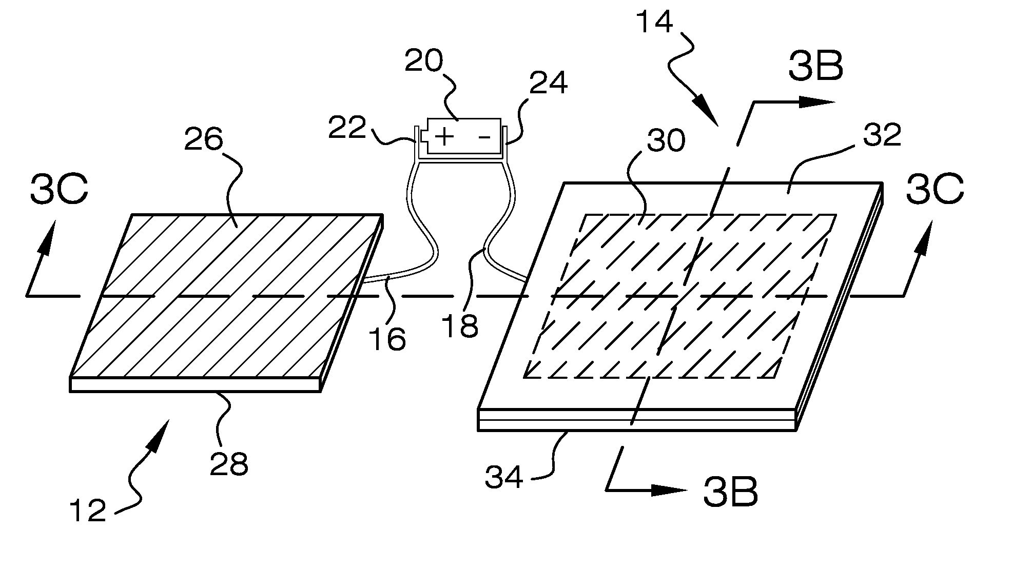
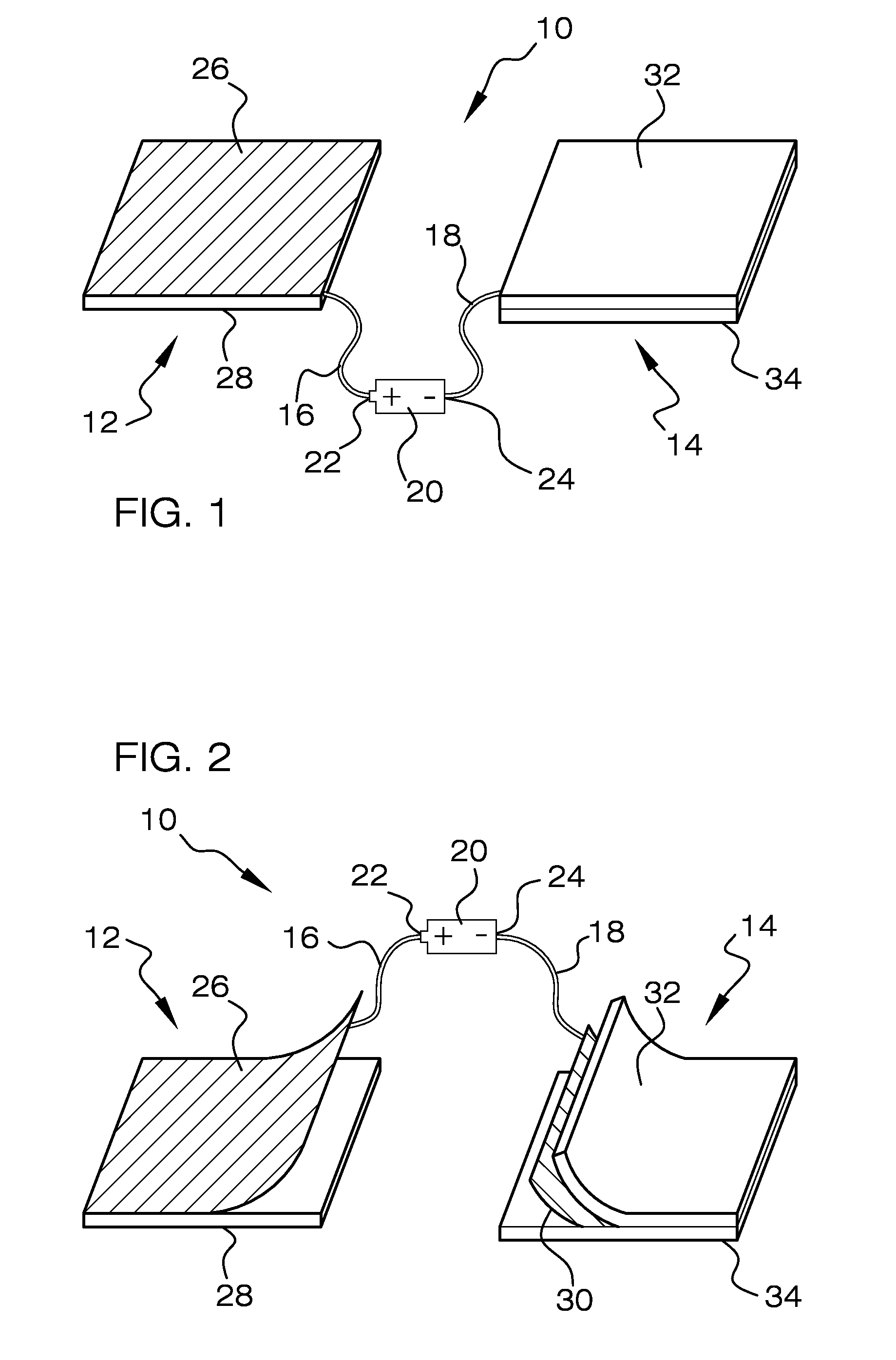
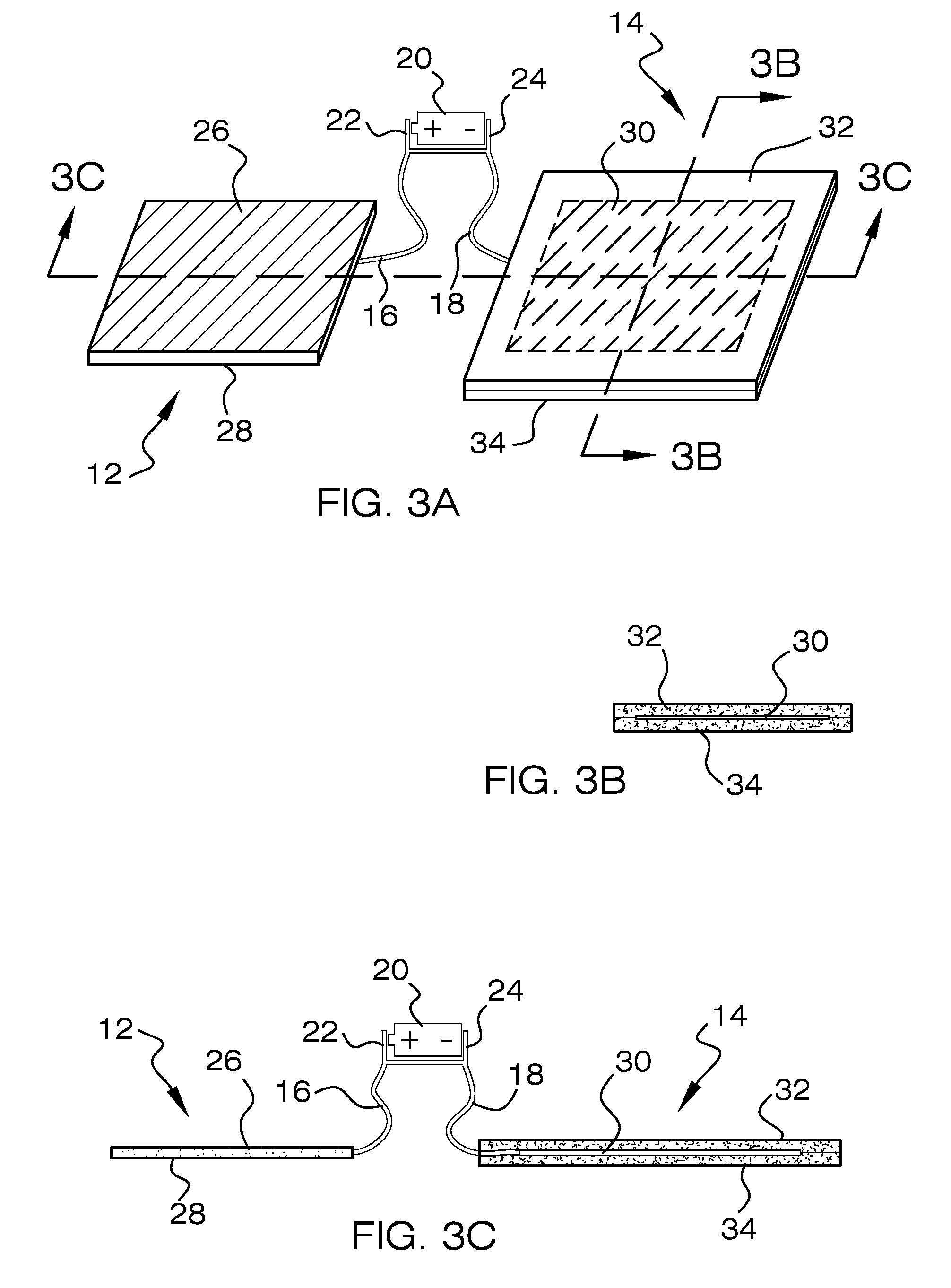
[0027]Referring now to the drawings, reference numeral 10 generally designates a pain relief device of the present invention. The device creates a type of electro-therapy for humans or animals for safely relieving pain and speeding recovery of an injury. The injury may be a sore joint or muscle. As shown in FIG. 1 the device includes two pad-type electrodes one being a thin flexible conducting pad 12, the second being a thin flexible insulted pad 14, a first insulated wire 16, a second insulated wire 18 and a low voltage direct current (DC) power source 20 having a positive (+) pole 22 and a negative (−) pole 24. The low voltage DC power source 20 may be any type of battery or multiple batteries, such as, conventional A, AA, AAA type batteries having a positive (+) pole 22 and a negative (−) pole 24. The voltages being used ...


PUM


Abstract

The Pain relief device used to relieve pain and promote faster healing in the bodies of humans and animals safely. A positive electrode touches the skin at the site of an injury and a negative electrode completely shielded with insulation is place on the skin at a spaced distance form the positive electrode. A low voltage direct current power source supplies a positive voltage to the positive electrode and a negative voltage to the negative electrode. Electrical stimulation occurs harmlessly, because the shielded negatively charged electrode or insulated pad, being an insulated sheet of aluminum foil produces an electric field in the body that is strong enough to cause a current to flow into the body at the site of the positive electrode. However, no current can flow at the site of the negative electrode because it is insulated and therefore no burns to the skin.

Description

CROSS-REFERENCE TO RELATED APPLICATIONS[0001]This application claims the benefit of U.S. application Ser. No. 10 / 419,300, filed Apr. 22, 2003, the entire of which is incorporated herein by reference.FIELD OF THE INVENTION[0002]The present invention relates generally to a pain relief device, and more particularly, relating to electrical stimulus pain relief device and method of the same.BACKGROUND OF THE INVENTION[0003]Pain relieving devices are known in the art. However, a new and improved pain relief device of a new construction and method of the same is needed.SUMMARY OF THE INVENTION[0004]The pain relief device creates a type of electro-therapy for people who have a sore joint or muscle and want relief from pain. The device consists of two pad-type electrodes, or pads, wired to a DC power source such as a battery; one pad to the positive (+) pole and the other pad to the negative (−) pole. The pads are broad, flat, and thin, and could be any shape or size above a square inch in a...

Claims


Application Information

Patent Timeline
Patent Type & Authority Patents(United States)
IPC IPC(8): A61N1/00A61N1/20A61N1/34
CPCA61N1/205A61N1/36021A61N1/0492A61N1/378
Inventor POLLOCK, FREDERICK WILLIAM
Owner POLLOCK FREDERICK WILLIAM
Why Eureka
Try Eureka