Input apparatus and control method for input apparatus

a control method and input technology, applied in pulse techniques, instruments, tactile signalling systems, etc., can solve the problems of difficult confirmation of auditory feedback, stress for operators, and inability of operators to obtain feedback to inputs, etc., to achieve realistic click sensation and realistic click sensation

Active Publication Date: 2017-05-02
KYOCERA CORP
View PDF29 Cites 0 Cited by
  • Summary
  • Abstract
  • Description
  • Claims
  • Application Information

AI Technical Summary

Benefits of technology

[0040]According to the present invention, if the pressure load on the touch sensor satisfies the standard to provide the tactile sensation, the touch face of the touch sensor vibrates so that a realistic click sensation is provided to an operator. Then, when the pressure load on the touch sensor satisfies the standard to provide the tactile sensation, the touch face of the touch sensor vibrates so that the release sensation corresponding to the click sensation is provided to the operator. Thereby, a realistic click sensation, similar to that obtained when a push-button switch is operated, is provided to the operator.

Problems solved by technology

Since the touch sensors themselves are not physically displaced when touched, an operator cannot obtain feedback to an input even though the touch input is received.
As a result, the operator is likely to input erroneously by touching the same spot multiple times, which may be stressful for the operator.
However, such auditory feedback may be difficult to be confirmed in a noisy environment and is not applicable when the equipment being used is in a silent mode.
Or, in using such visual feedback, if the input object displayed on the display unit is small, the operator may not be able to confirm the change in the display state, as a view of the input object is blocked by a finger, particularly when the operator is inputting by the finger.

Method used


Image

  • Input apparatus and control method for input apparatus
  • Input apparatus and control method for input apparatus
  • Input apparatus and control method for input apparatus

Examples


first embodiment

[0084]FIG. 5 is a block diagram illustrating a schematic constitution of an input apparatus according to a first embodiment of the present invention. This input apparatus has a touch sensor 11, a load detection unit 12, a tactile sensation providing unit 13, a display unit 14, and a control unit 15 for controlling overall operations. The touch sensor 11 receives an input to the display unit 14 by a finger and the like and may be, for example, of a known type such as a resistive film type, a capacitive type, an optical type and the like. The load detection unit 12 detects the pressure load applied to the touch face of the touch sensor 11 and may include an element such as, for example, a strain gauge sensor, a piezoelectric element or the like, which linearly reacts to a load. The tactile sensation providing unit 13 vibrates the touch sensor 11 and may include, for example, a piezoelectric vibrator. The display unit 14 displays an input object of an input button or the like such as t...

second embodiment

[0100]FIG. 10 and FIG. 11 illustrate an input apparatus according to a second embodiment of the present invention; FIG. 10 is a block diagram of a schematic constitution and FIG. 11 is a front view. This input apparatus is mounted on, for example, the mobile terminal and, as illustrated in FIG. 10, has a touch sensor 41 for receiving an input, a display unit 43 for displaying information based on an input position on the touch sensor 41, a load detection unit 44 for detecting a pressure load on the touch sensor 41, a tactile sensation providing unit 45 for vibrating the touch sensor 41 and a control unit 46 for controlling overall operations.

[0101]As illustrated in FIG. 11, a plurality of input objects 41a such as numeric keys are already provided, printed, adhered or the like, on the touch sensor 41. Accordingly, in the input apparatus according to the present embodiment, each of the input objects 41a constitutes the touch face. In order to prevent an erroneous input pressing a plu...

third embodiment

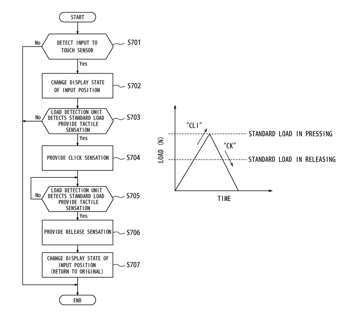
[0120]Incidentally, the input apparatus used in the mobile terminals, for example, is often used for a so-called repetitive tap to continuously input the same input object in inputting a phone number, a message and the like. In such a case, if the touch sensor 11 is vibrated in the predetermined vibration pattern not only in pressing but also in releasing as illustrated in FIG. 17, it is necessary to appropriately set the predetermined standard load in releasing to provide the tactile sensation.

[0121]That is, when the human quickly performs continuous input, a next input is generally started before the pressure load returns to “0” and the maximum load in pressing varies. At this point, in a case where the standard load in pressing to provide the tactile sensation and that in releasing are set to be equal as described in the first embodiment, for example, if the pressure load is pulled back at the standard load during continuous input as illustrated in FIG. 18, the tactile sensation ...


PUM


Abstract

An input apparatus has a touch sensor 11 for an input, a load detection unit 12 to detect a pressure load on a touch face 11a of the sensor 11, a tactile sensation providing unit 13 to vibrate the touch face 11a, and a control unit 15 to control drive of the tactile sensation providing unit 13, when the detected pressure load satisfies a standard to provide a tactile sensation, to provide a click sensation to an object (means) pressing the touch face 11a. The control unit 15 drives the tactile sensation providing unit 13, when the detected pressure load satisfies the standard after the click sensation is provided in pressing, to provide a release sensation corresponding to the click sensation to the object. Thereby, a realistic click sensation similar to that in operating a push-button switch is provided when an operator operates the touch sensor.

Description

CROSS REFERENCE TO RELATED APPLICATION[0001]This application claims priority to and the benefit of Japanese Patent Application No. 2009-177074 filed on Jul. 29, 2009, the entire contents of which are incorporated herein by reference.TECHNICAL FIELD[0002]The present invention relates to an input apparatus having a touch sensor and a control method for an input apparatus.BACKGROUND ART[0003]In recent years, input apparatuses having touch sensors such as touch panels, touch switches or the like are popularly used as input apparatuses such as operation units, switches and the like for receiving input operations by a user in mobile terminals such as mobile phones, information equipments such as calculator, ticket vending machines, home electric appliances such as microwaves, TV sets, lighting equipments, industrial equipments (FA equipments) and the like.[0004]There are known a variety of types of those touch sensors, such as a resistive film type, a capacitive type, an optical type and ...

Claims


Application Information

Patent Timeline
Patent Type & Authority Patents(United States)
IPC IPC(8): G08B6/00H03K17/96G06F3/01G06F3/041G06F3/0488G06F3/0489
CPCH03K17/9625G06F3/016G06F3/0414G06F3/0416H03K2217/96062G06F3/0412G06F3/04142
Inventor AONO, TOMOTAKE
Owner KYOCERA CORP
Why Eureka
Try Eureka