Electromagnetic Linear Actuator

a linear actuator and electric motor technology, applied in the direction of support/enclose/case, magnetic circuit shape/form/construction, electrical equipment, etc., can solve the problem of large size of linear actuators, achieve realistic click sensation, enhance the degree of immersion, and intensify vibration

Pending Publication Date: 2021-10-21
NUI LAB GMBH
View PDF4 Cites 1 Cited by
  • Summary
  • Abstract
  • Description
  • Claims
  • Application Information

AI Technical Summary

Benefits of technology

[0036]A substantial advantage of the present invention, in particular the embodiment with at least one end element, preferably implemented as a cover, lies in the fact that an extremely strong actuator exists, thus intensive vibrations, for example, can be produced thereby.
[0037]Furthermore, the actuator according to the invention makes possible a realistic click sensation, especially in the case of immovable, capacitive user interfaces. Thus a switch characteristic, for example, or the feedback of a switch or similar to a user can be imitated by means of the inventive actuator on surfaces or similar.
[0038]An additional aspect of the invention lies in an operating element with an inventive actuator according to the present description. Haptic and / or acoustic signals, which the actuator according to the invention transmits by means of mechanical movement, preferably vibration, in particular to the surface of the operating element, can hereby be emitted to a user operating the operating element.
[0039]Another aspect of the invention lies in a bicycle grip or a handlebar of a bicycle with an inventive actuator according to the present description. For example, haptic information from navigation equipment or similar, for example, can be transmitted to the bicycle rider in such a way.
[0040]Moreover, another aspect of the invention consists in a chair, in particular a gaming chair, with an inventive actuator according to the present description. Thus on the basis of haptic signals to a user sitting on the chair, preferably in computer games, for example in the case of shots, explosions, etc., the degree of immersion can be enhanced, especially in the context of virtual reality.

Problems solved by technology

Nevertheless, such linear actuators have a large number of disadvantages.

Method used


Image

  • Electromagnetic Linear Actuator
  • Electromagnetic Linear Actuator
  • Electromagnetic Linear Actuator

Examples


Embodiment Construction

[0053]Identical elements are identified by the same reference characters in the Figs. For clarity, reference characters are not provided in all Figs., especially where elements have already been identified previously. If identical elements occur several times in an embodiment depicted by a figure, for example because a component is present multiple times, then such elements are differentiated by means of apostrophes.

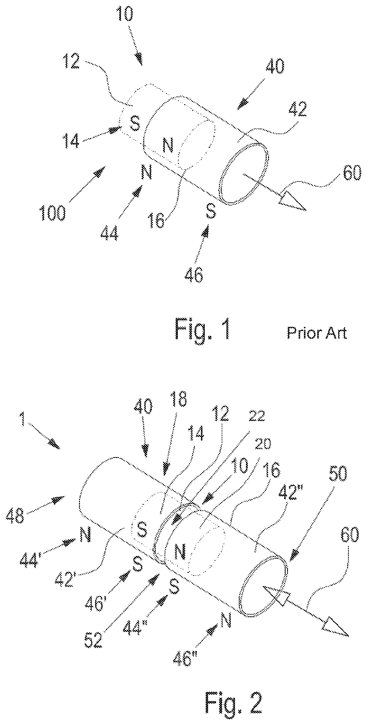
[0054]The solenoid actuator 100 of the prior art from FIG. 1 was already discussed at the beginning.

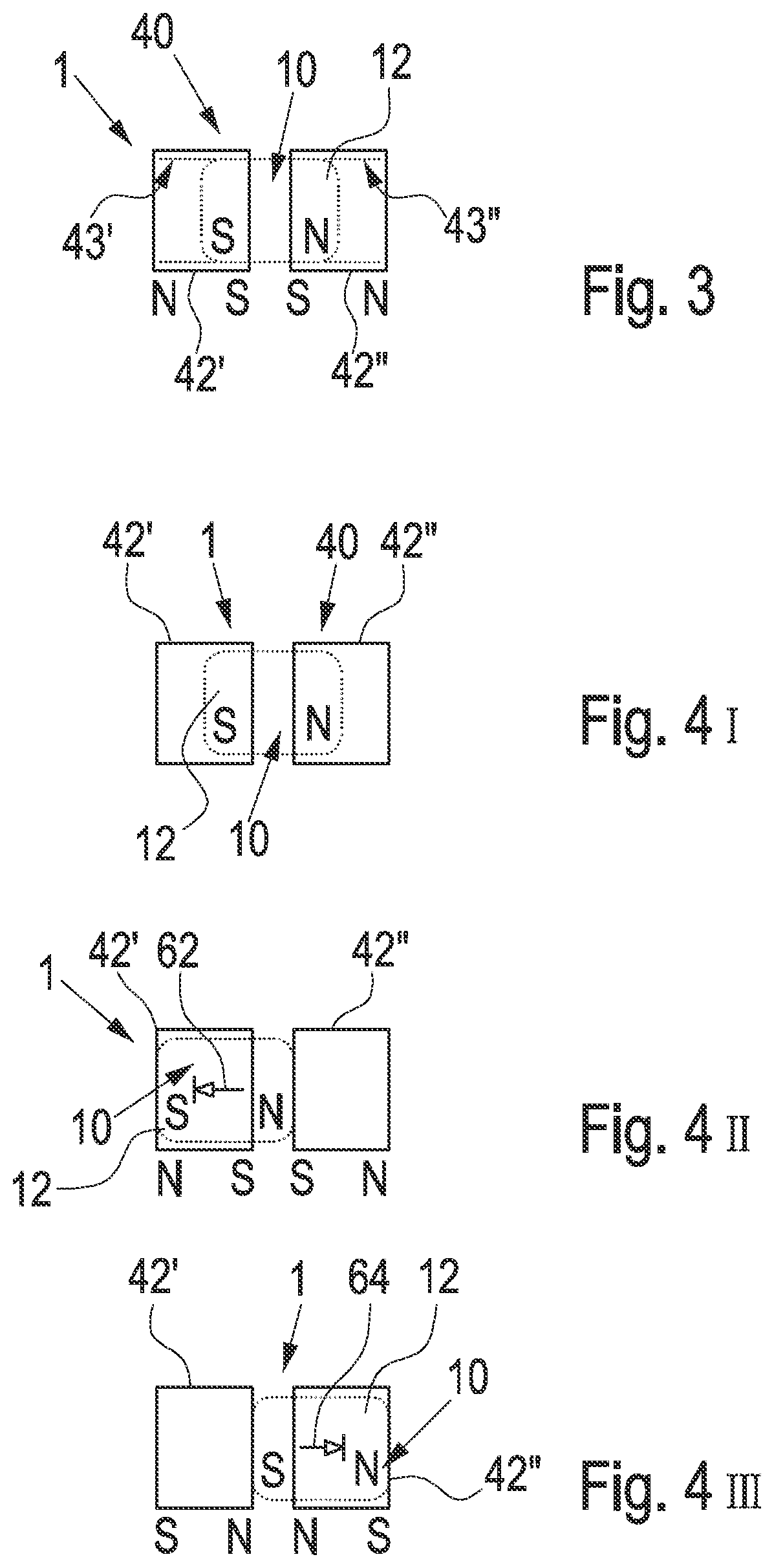
[0055]The electromagnetic linear actuator 1 depicted in FIG. 2 comprises an oscillator 10 with a permanent magnet 12. The oscillator 10 corresponds here to the first element of the electromagnetic linear actuator 1. The permanent magnet 12 has the form of a solid cylinder, with a circle as a base. Located on one side 18 of the oscillator is the oscillator pole 14, this being a south pole (S) in this case. Located on the other side 20 of the oscillator accordingly is the ot...


PUM


Abstract

An electromagnetic linear actuator, which comprises a first and a second element. One element is a magnetic oscillator with at least one magnet, and the other element is a magnetic stator with at least one magnet. The two elements are movable relatively linearly to one another and the magnetization directions of the oscillator and of the stator are parallel. Either the stator comprises two opposing identical stator poles or the oscillator comprises two opposing identical oscillator poles. Furthermore, a method for producing a mechanical movement by means of an actuator. Either magnetization of a stator of the actuator takes place such that the stator comprises two opposing identical stator poles or magnetization of an oscillator of the actuator takes place such that the oscillator comprises two opposing identical oscillator poles.

Description

CROSS-REFERENCE TO RELATED APPLICATIONS[0001]This application is the United States national phase of International Application No. PCT / EP2019 / 072351 filed Aug. 21, 2019, and claims priority to German Patent Application No. 10 2018 214 102.9 filed Aug. 21, 2018, the disclosures of which are hereby incorporated by reference in their entirety.BACKGROUND OF THE INVENTIONField of the Invention[0002]The invention relates to an electromagnetic linear actuator and a method for producing a mechanical movement, in particular a vibration, by means of an actuator.Description of Related Art[0003]Linear actuators are used as standard to produce mechanical movements. A mechanical movement is preferably a continuous linear movement, for example a displacement of objects relative to one another. For example, the function of a linear motor can be executed hereby and objects thus put into translatory motions, for example. It is also possible to produce a vibration and thus a haptic (and / or acoustic) s...

Claims


Application Information

Patent Timeline
Patent Type & Authority Applications(United States)
IPC IPC(8): H02K33/16
CPCH02K33/16H02K33/12H02K41/02H02K41/031H02K5/24H02K1/34
Inventor JAGODZINSKI, RON
Owner NUI LAB GMBH
Why Eureka
Try Eureka