
Method for mounting an acoustic panel in a housing of a turbomachine and turbomachine comprising an acoustic panel

a technology of acoustic panel and acoustic panel, which is applied in the direction of machines/engines, mechanical devices, power plant exhaust arrangements, etc., can solve the problems of increasing the mass of the turbine engine, generating noise, and presenting a disadvantage, so as to reduce the weight of the turbine engine and avoid damage. , the effect of improving the acoustic damping

Active Publication Date: 2017-05-23
SN DETUDE & DE CONSTR DE MOTEURS DAVIATION S N E C M A
View PDF10 Cites 0 Cited by
  • Summary
  • Abstract
  • Description
  • Claims
  • Application Information

AI Technical Summary

Benefits of technology

The patent describes a method for mounting an acoustic panel in a fan of a turbine engine. By using a cylindrical acoustic panel with a longitudinal slot and attaching it to the fan using glue, the panel can be easily mounted without risking damage. This method reduces the weight of the turbine engine and improves the acoustic damping. Additionally, the longitudinal slot allows for consistent acoustic damping with the circumference of the panel. The acoustic panel can be an annular part or an angular sector, depending on the needs. The technical effects of this patent include improved acoustic damping and reduced weight of the turbine engine.

Problems solved by technology

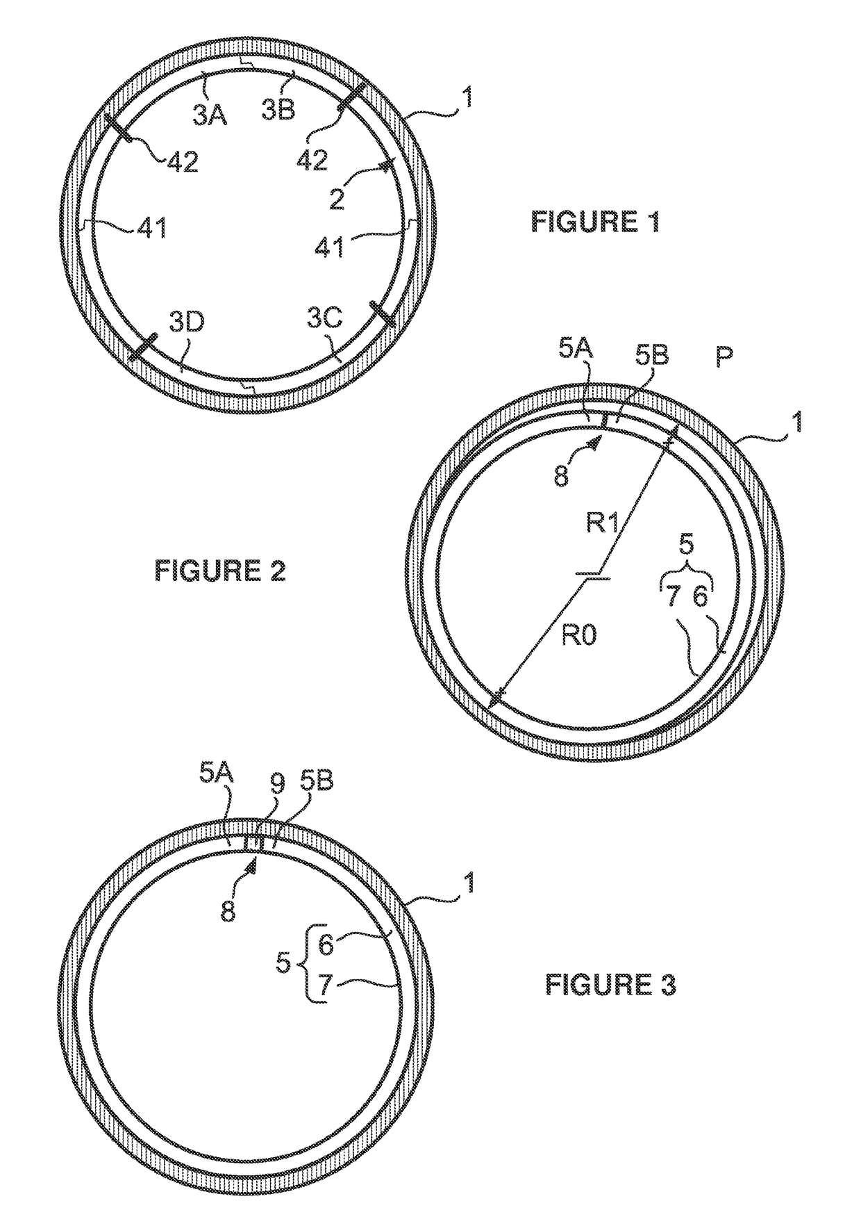
In practice, the tangential linking means 41 on the interfaces between the acoustic modules 3A, 3B, 3C, 3D and the fixing screws 42 generate noise when the turbine engine is in operation; given the fact that turbine engines have to comply with increasingly strict noise standards, this presents a disadvantage.
Moreover, the use of fixing screws 4 increases the mass of the turbine engine, and this presents another disadvantage.

Method used


Image

  • Method for mounting an acoustic panel in a housing of a turbomachine and turbomachine comprising an acoustic panel
  • Method for mounting an acoustic panel in a housing of a turbomachine and turbomachine comprising an acoustic panel
  • Method for mounting an acoustic panel in a housing of a turbomachine and turbomachine comprising an acoustic panel

Examples


Embodiment Construction

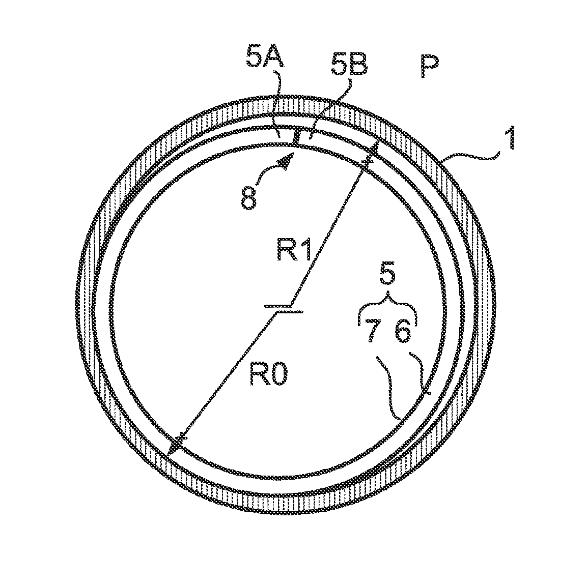
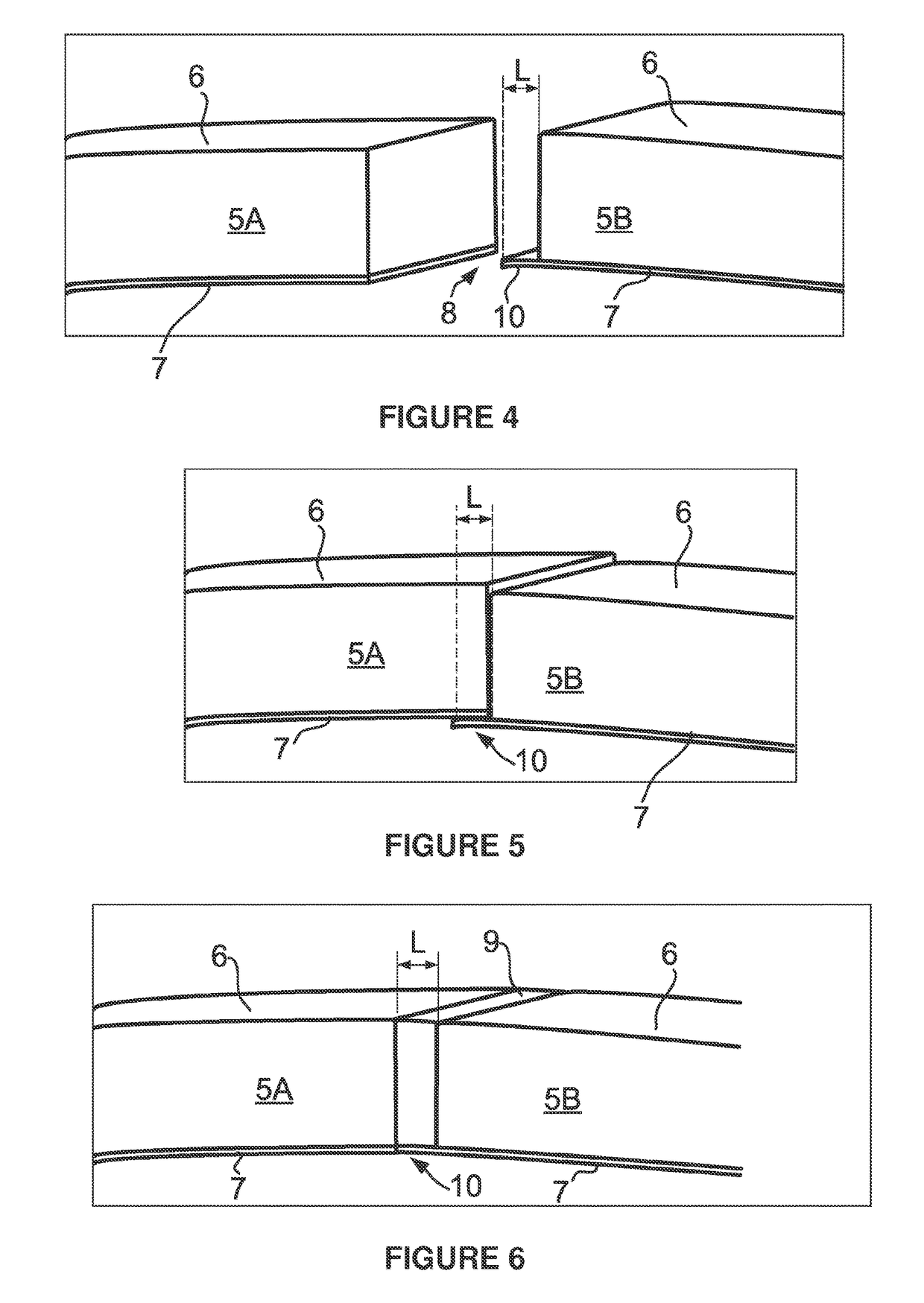
[0029]The following will describe how the invention can be used to mount an acoustic panel on the inner surface of a casing of a turbine engine for aircraft. In this example, with reference to FIGS. 2 and 3, the turbine engine comprises a fan casing 1 which extends longitudinally along the axis of the turbine engine and has a circular cross section with a predetermined inner radius R1. The fan casing 1 is capable of housing a fan which is rigidly connected to an axial shaft of the turbine engine (not shown).

[0030]In order to limit the noise generated by the turbine engine, the inner surface of the fan casing 1 is covered by a cylindrical acoustic panel 5, which is formed in one piece, is annular in shape and extends longitudinally with respect to the axis of the turbine engine. An acoustic panel 5, which is formed in one piece, advantageously allows the noise generated to be reduced in comparison with an acoustic panel which comprises modules. As shown in FIG. 3, the outer radius of...


PUM


Abstract

A method for mounting an acoustic panel on the inner surface of an annular housing of an axial turbomachine, the cylindrical acoustic panel comprising at least one longitudinal slot so as to define two opposing ends, the method comprising: bringing the two opposing ends closer together so as to reduce the cylinder radius of the acoustic panel; inserting the acoustic panel into the fan casing when the opposing ends are close together; deploying the opposing ends so as to increase the cylinder radius of the acoustic panel; and securing the acoustic panel to the housing by gluing.

Description

GENERAL TECHNICAL FIELD AND PRIOR ART[0001]The present invention relates to the field of reducing the noise generated by a turbine engine and, more particularly, to attaching an acoustic panel to the inner surface of a casing of a turbine engine for aircraft.[0002]Conventionally, a turbine engine for aircraft allows an air flow to accelerate axially upstream to downstream in order to generate a thrust for the aircraft on which the turbine engine is mounted. The terms “upstream” and “downstream” are hereinafter defined in relation to the direction in which the air flow circulates in the turbine engine. The terms “inner” and “outer” are hereinafter defined in relation to the axis of the turbine engine. A longitudinal cylinder thus comprises an inner surface which faces its axis and an outer surface which is opposite its inner surface.[0003]A turbine engine comprises a rotary shaft which, at its upstream end, terminates in a fan so as to set said fan into rotation inside a fan casing o...

Claims


Application Information

Patent Timeline
Patent Type & Authority Patents(United States)
IPC IPC(8): F02C7/24F02C7/045F02K1/82
CPCF02C7/24F02C7/045F02K1/827Y02T50/671Y02T50/60B64D33/02B64D33/04F02K1/82
Inventor SFARTI, FRANCOISMARLIN, FRANCOIS MARIE PAUL
Owner SN DETUDE & DE CONSTR DE MOTEURS DAVIATION S N E C M A
Learn More