Touch panel

a technology of touch panel and sensor, which is applied in the field of touch panel, can solve problems such as errors in the operation of proximity sensors, and achieve the effects of reducing sensing errors, improving reliability of touch panel, and reducing scatter reflection

Inactive Publication Date: 2017-05-23
LG INNOTEK CO LTD
View PDF17 Cites 7 Cited by
  • Summary
  • Abstract
  • Description
  • Claims
  • Application Information

AI Technical Summary

Benefits of technology

[0011]According to the touch panel, the black print layer is disposed to fill the step difference of white print layer, so that the quantity of infrared light emitted from the sensing part and scattered on the white print layer may be reduced. That is, according to the touch panel of the embodiment, when the light emitted from the light emitting part of the sensing part is incident on the first light receiving part of the print layer, the scattered reflection may be reduced due to the white print layer, so that undesired light may be inhibited from being incident on the second light receiving part due to the scattered reflection.
[0012]Thus, the touch panel according to the embodiment may reduce errors of the sensing part, so that the reliability of the touch panel may be substantially improved.

Problems solved by technology

However, when the print layer disposed in the UA is a white printed layer, the light emitted from the sensing part is scattered to be unintentionally incident upon the light receiving part, so that an error may occur in the operation of the proximity sensor.

Method used


Image

  • Touch panel
  • Touch panel
  • Touch panel

Examples


Embodiment Construction

[0020]In the following description of the embodiments, it will be understood that, when a layer (or film), a region, a pattern, or a structure is referred to as being “on” or “under” another substrate, another layer for film), another region, another pad, or another pattern, it can be “directly” or “indirectly” on the other substrate, layer (or film), region, pad, or pattern, or one or more intervening layers may also be present. Such a position of the layer has been described with reference to the drawings.

[0021]The thickness and size of each layer shown in the drawings may be exaggerated, omitted or schematically drawn for the purpose of convenience or clarity. In addition, the size of elements does not utterly reflect an actual size.

[0022]Hereinafter, the embodiments will be described with reference to the accompanying drawings.

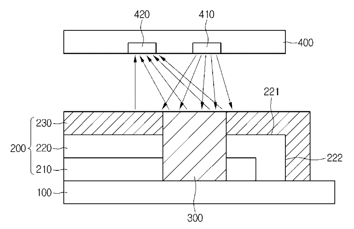
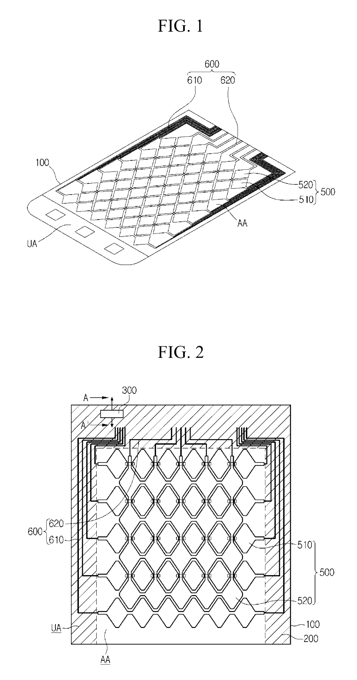
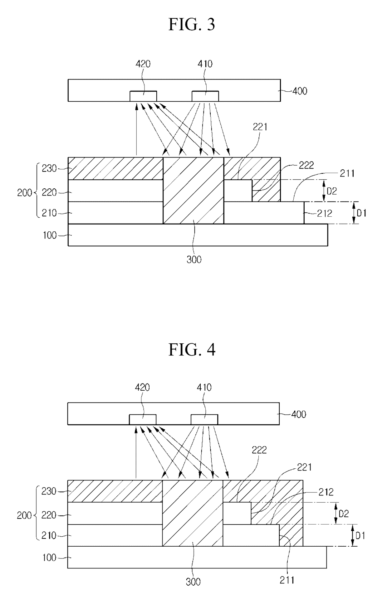
[0023]Referring to FIGS. 1 to 4, a touch panel according to the embodiment may include a cover window 100, a print layer 200 provided on the cover window ...


PUM


Abstract

A touch panel according to the embodiment includes a cover window including an active area and an unactive area; a print layer on the unactive area; a sensing part on the unactive area to emit light toward the print layer; and a first light receiving part on the print layer to receive the light, wherein the print layer includes a first print layer on the cover window; a second print layer formed on the first print layer while forming a step difference with respect to the first print layer; and a third print layer formed on the second print layer while filling the step difference.

Description

CROSS-REFERENCE TO RELATED APPLICATION[0001]This application claims the benefit under 35 U.S.C. §119 of Korean Patent Application No. 10-2012-0133890, filed Nov. 23, 2012, which is hereby incorporated by reference in its entirety.BACKGROUND[0002]The embodiment relates to a touch panel.[0003]Recently, a touch panel, which performs an input function through the touch of an image displayed on a display device by an input device such as a stylus pen or a hand, has been applied to various electronic appliances.[0004]The touch panel may be representatively classified into a resistive touch panel and a capacitive touch panel. In the resistive touch panel, the position of the touch point is detected by detecting the variation of resistance according to the connection between electrodes when pressure is applied to an input device. In the capacitive touch panel, the position of the touch point is detected by detecting the variation in capacitance when a finger of the user is touched on the ca...

Claims


Application Information

Patent Timeline
Patent Type & Authority Patents(United States)
IPC IPC(8): G06F3/041G06F3/042
CPCG06F3/041G06F3/0421G06F2203/04101G06F2203/04106G06F3/0446G06F3/042
Inventor AHN, JI SUNG
Owner LG INNOTEK CO LTD
Why Eureka
Try Eureka