Wheel cover assembly

a technology for wheels and covers, applied in the direction of wheel protection, vehicle components, multi-purpose tools, etc., can solve the problems of expensive repair/replacement, affecting the practicality of all circumstances, and affecting the connection of wheels on chairs, shelves, tables,

Active Publication Date: 2017-06-06
SOLIMAN ALAAELDIN
View PDF10 Cites 10 Cited by
  • Summary
  • Abstract
  • Description
  • Claims
  • Application Information

AI Technical Summary

Benefits of technology

[0007]The neck portion comprises an angled collar on the outer neck wall; and a top wall connected to the angled collar and the inner neck wall. The lip portion comprises an angled upper surface such that a thickness of an end of the lip portion may be less than a thickness of a junction of the lip portion with the wheel housing. The assembly further comprises a pair of interfaces configured at the connection of the first half wheel cover with the second half wheel cover. The plurality of tabs bridge the pair of interfaces. The pair of interfaces comprises a first interface and a second interface, and wherein the first interface and the second interface are oppositely positioned from one another. Each of the first half wheel cover and the second half wheel cover comprise a pair of tabs positioned on an inner surface of the middle portion and bridging the first interface. Each of the first half wheel cover and the second half wheel cover comprise a tab positioned on the inner surface of the middle portion and bridging the second interface. The pair of clips bridge the pair of interfaces. The wheel housing may be hollow. The neck portion may be offset from a centroid of the wheel housing.

Problems solved by technology

Wheels connected on chairs, shelves, racks, beds, tables, and other moveable objects are often impeded by cords, wires, or other similar obstacles.
Sometimes the wheels, such as caster wheels, can roll over these obstacles, but often time the obstacles drag along or become entangled with the wheels.
While it would be desirable to simply remove any obstacles from the path that the wheels / objects take along a particular route, this may not be practical in all circumstances.
When beds are being moved, they often come into contact with these cords and wires, which can cause damage to the cords, wires, or the diagnostic machines themselves, and which results in a very expensive repair / replacement.

Method used


Image

  • Wheel cover assembly
  • Wheel cover assembly
  • Wheel cover assembly

Examples


Embodiment Construction

[0027]The embodiments herein and the various features and advantageous details thereof are explained more fully with reference to the non-limiting embodiments that are illustrated in the accompanying drawings and detailed in the following description. Descriptions of well-known components and processing techniques are omitted so as to not unnecessarily obscure the embodiments herein. The examples used herein are intended merely to facilitate an understanding of ways in which the embodiments herein may be practiced and to further enable those of skill in the art to practice the embodiments herein. Accordingly, the examples should not be construed as limiting the scope of the embodiments herein.

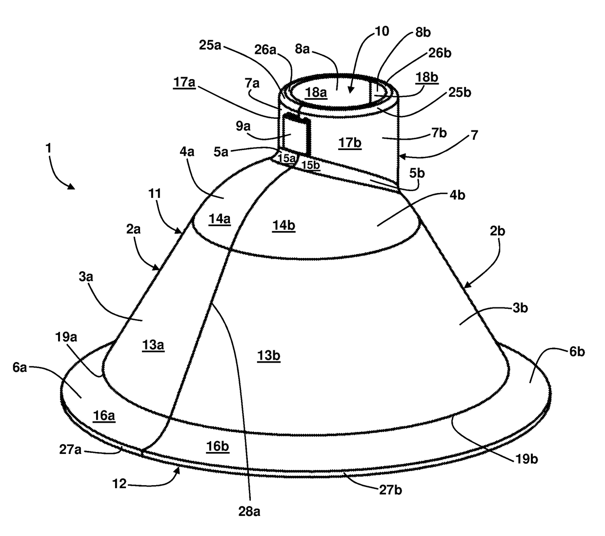
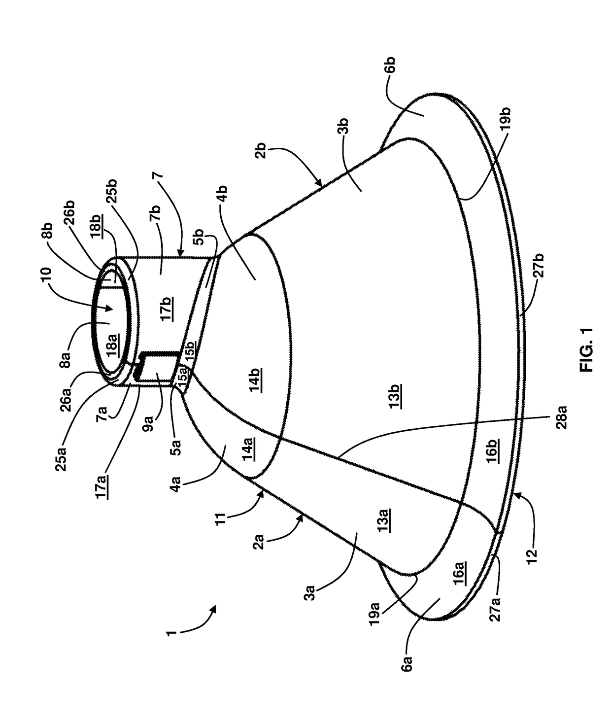
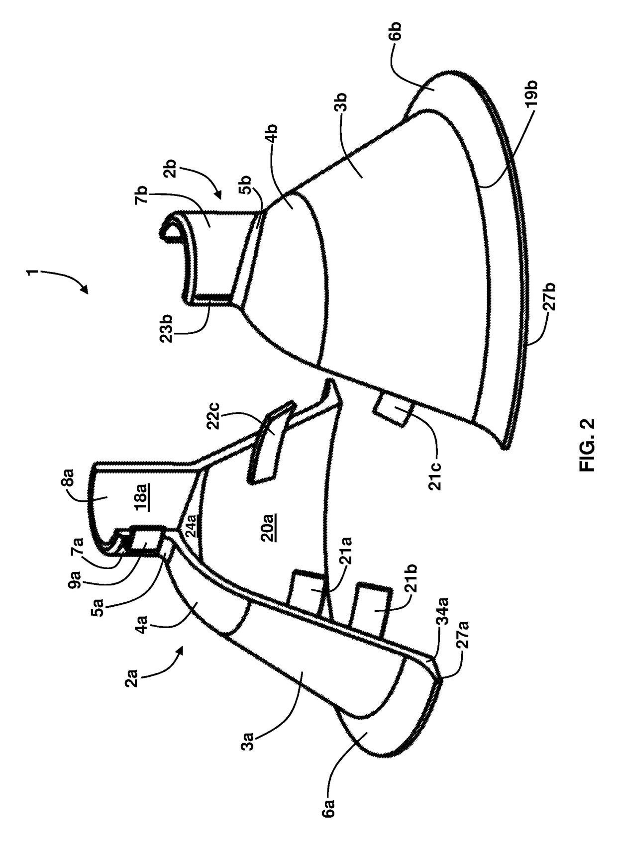
[0028]The embodiments herein provide a wheel cover assembly that surrounds a wheel to allow the wheel to move freely without getting entangled by chords, wires, and other obstacles on the ground. Referring now to the drawings, and more particularly to FIGS. 1 through 17, where similar reference...


PUM


Abstract

A wheel cover assembly includes a wheel housing configured to house a wheel mechanism; a neck portion upwardly extending from the wheel housing, wherein the neck portion includes a hollow channel that extends into the wheel housing; a pair of clips configured on the neck portion; and a lip portion extending from a lower portion of the wheel housing. The wheel housing includes a first half wheel cover; a second half wheel cover; and a plurality of tabs connected to each of the first half wheel cover and the second half wheel cover, wherein the plurality of tabs selectively align together upon connection of the first half wheel cover with the second half wheel cover.

Description

BACKGROUND[0001]Technical Field[0002]The embodiments herein generally relate to wheel accessories, and more particularly to wheel covers.[0003]Description of the Related Art[0004]Wheels connected on chairs, shelves, racks, beds, tables, and other moveable objects are often impeded by cords, wires, or other similar obstacles. Sometimes the wheels, such as caster wheels, can roll over these obstacles, but often time the obstacles drag along or become entangled with the wheels. While it would be desirable to simply remove any obstacles from the path that the wheels / objects take along a particular route, this may not be practical in all circumstances. For example, in hospital settings, beds or gurneys almost always have wheels to allow for easy mobility of patients from room-to-room. However, hospital rooms are replete with cords and wires emanating from various types of diagnostic machines. When beds are being moved, they often come into contact with these cords and wires, which can ca...

Claims


Application Information

Patent Timeline
Patent Type & Authority Patents(United States)
IPC IPC(8): B60B7/10B60B7/04B60B33/00
CPCB60B7/10B60B7/04B60B33/0028B60B2200/22B60B2200/24B60B2200/20B60B2900/551B60B2200/242B60B2200/26Y10T16/216B60R19/00B60B33/00B60R2019/002
Inventor SOLIMAN, ALAAELDIN
Owner SOLIMAN ALAAELDIN
Why Eureka
Try Eureka