Superconducting accelerating cavity and electropolishing method for superconducting accelerating cavity

a superconducting accelerating cavity and electropolishing technology, applied in the direction of accelerators, electrical devices, etc., can solve the problems of degrading the performance of accelerating charged particles, and achieve the effect of easy electropolishing again

Active Publication Date: 2017-06-06
MITSUBISHI HEAVY IND MACHINERY SYST LTD
View PDF10 Cites 1 Cited by
  • Summary
  • Abstract
  • Description
  • Claims
  • Application Information

AI Technical Summary

Benefits of technology

[0033]According to the present invention, it is possible to provide a superconducting accelerating cavity which can be easily electropolished again even after installation of a refrigerant tank, and an electropolishing method for a superconducting accelerating cavity.

Problems solved by technology

When the inner surface of the main body of the superconducting accelerating cavity is not smooth, or when impurities are present on the inner surface of the main body, heat generation or electrical discharge is induced, which degrades the performance of accelerating the charged particles.

Method used


Image

  • Superconducting accelerating cavity and electropolishing method for superconducting accelerating cavity
  • Superconducting accelerating cavity and electropolishing method for superconducting accelerating cavity
  • Superconducting accelerating cavity and electropolishing method for superconducting accelerating cavity

Examples


first embodiment

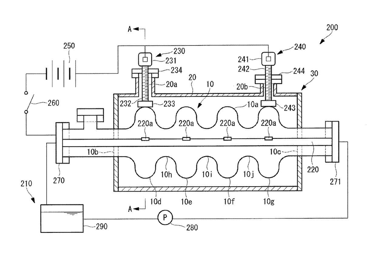
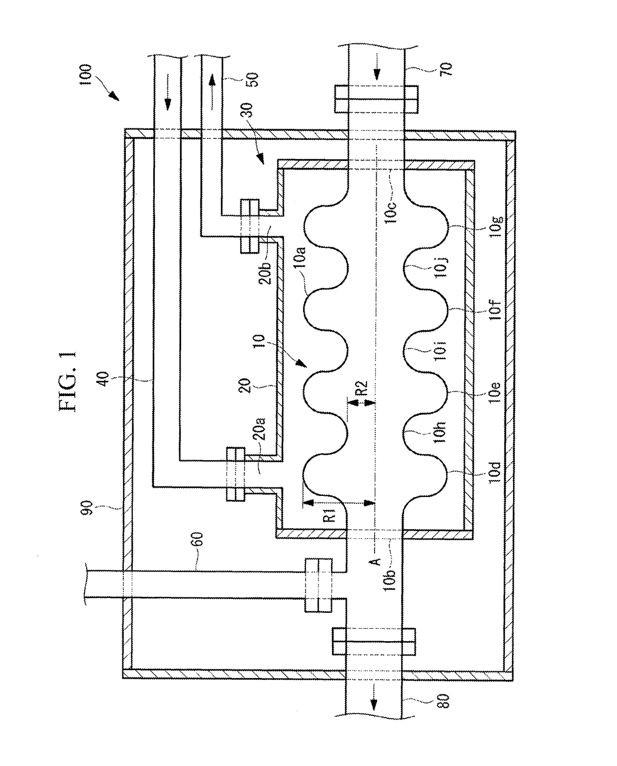
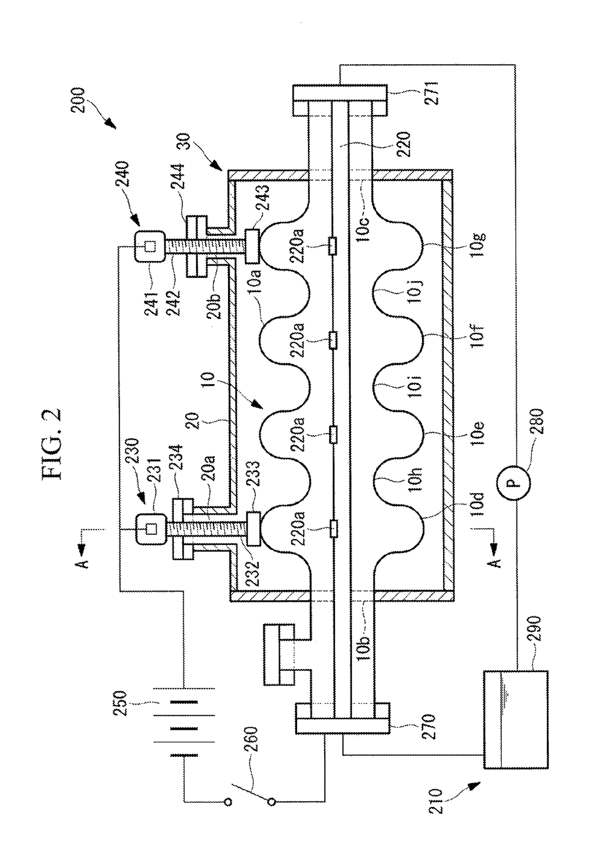
[0041]In the following, a superconducting accelerator 100 of a first embodiment of the present invention will be described by using FIG. 1. FIG. 1 is a longitudinal cross-sectional view showing the configuration of the superconducting accelerator of the first embodiment of the present invention.

[0042]In FIG. 1, the superconducting accelerator 100 includes a superconducting accelerating cavity 30, and a vacuum vessel 90 housing the superconducting accelerating cavity 30. The superconducting accelerating cavity 30 includes a cavity main body 10 formed of a superconducting material such as niobium (Nb) into a cylindrical shape, and a refrigerant tank 20 installed around the cavity main body 10. The refrigerant tank 20 stores a refrigerant which is supplied from the outside through a supply port 20a into a space created between the refrigerant tank and the outer circumferential surface of the cavity main body 10. As the refrigerant, for example, liquid helium is used.

[0043]The outer cir...

second embodiment

[0094]In the following, a cavity main body 600 of a superconducting accelerator of a second embodiment will be described by using FIG. 6. FIG. 6 is a view showing the cavity main body 600 of a superconducting accelerating cavity of the second embodiment of the present invention. Although the refrigerant tank is provided around the cavity main body 600, the refrigerant tank is not shown in FIG. 6.

[0095]The second embodiment is a modified example of the first embodiment; unless otherwise described in the following, the second, embodiment is the same as the first embodiment, and description thereof will be omitted.

[0096]The coating thickness of the metal coating layer 10a of the first embodiment is substantially constant regardless of the position in the direction of the central axis of the cavity main body 10. In contrast, the coating thickness of a metal coaxing layer 600a of the second embodiment varies depending on the position in the direction of the central axis A of the cavity m...


PUM

PropertyMeasurementUnit
superconductingaaaaaaaaaa
conductivityaaaaaaaaaa
diameteraaaaaaaaaa

Abstract

Provided is a superconducting accelerating cavity 30 including: a cavity main body 10 formed of a superconducting material into a cylindrical shape; and a refrigerant tank 20 installed around the cavity main body 10 and storing a refrigerant which is supplied from the outside through a supply port 20a into a space formed between the refrigerant tank and the outer circumferential surface of the cavity main body 10, wherein the outer circumferential surface of the cavity main body 10 is coated with a metal coating layer 10a having a higher conductivity than the superconducting material.

Description

TECHNICAL FIELD[0001]The present invention relates to a superconducting accelerating cavity and an electropolishing method for a superconducting accelerating cavity.BACKGROUND ART[0002]A superconducting accelerating cavity is a device for accelerating charged particles such as electrons, positrons, and protons by means of an accelerating electric field generated inside the cavity by an input of high-frequency power. When the inner surface of the main body of the superconducting accelerating cavity is not smooth, or when impurities are present on the inner surface of the main body, heat generation or electrical discharge is induced, which degrades the performance of accelerating the charged particles.[0003]It is a known practice to perform electropolishing in order to smooth the inner surface of the main body of the superconducting accelerating cavity and remove impurities from the inner surface (e.g., see PTL 1). Eiectropolishing of the superconducting accelerating cavity is perform...

Claims


Application Information

Patent Timeline
Patent Type & Authority Patents(United States)
IPC IPC(8): H05H7/20C25F3/26
CPCH05H7/20C25F3/26
Inventor HARA, HIROSHI
Owner MITSUBISHI HEAVY IND MACHINERY SYST LTD
Why Eureka
Try Eureka