High-temperature superconducting tape

Active Publication Date: 2012-10-04
KOREA ELECTROTECH RES INST
View PDF7 Cites 4 Cited by
  • Summary
  • Abstract
  • Description
  • Claims
  • Application Information

AI Technical Summary

Benefits of technology

[0010]Accordingly, the present invention has been devised to solve the above-mentioned problems, and an object of the present invention is to provide a high-temperature superconducting tape, the critical current characteristics of which are improved because a stainless steel substrate, which is easily electropolished, is used and because of adjusting the composition ratio and crystal grain size of the stainless steel substrate.

Problems solved by technology

Particularly, when nickel (Ni), which is contained in the metal substrate in large quantity, is diffused into YBCO lattices, the superconducting characteristics of YBCO are rapidly deteriorated, so that it is required to prevent nickel (Ni) from being diffused into the YBCO superconducting layer using the buffer layer formed between the metal substrate and the YBCO superconducting layer.
Such a diffusion barrier layer made of alumina is problematic in that, although the diffusion of metal components of a metal substrate into a superconducting layer can be prevented to some degree, the diffusion of the metal components into the superconducting layer with crystal grains cannot be completely prevented.
Further, this diffusion barrier layer is problematic in that, since its surface roughness is not good, it is required to make a template relatively thick in order to deposit a high-grade superconducting layer on a metal substrate, and thus it takes a lot of time to manufacture a superconducting tape.
Therefore, there are problems in that the cost of fabricating the template increases, and in that the resulting superconducting tape is thick.
However, there are also problems in that it is difficult to realize the common use of these stainless steel substrates because the critical current density and surface roughness improvements are falling short, and because the surface roughness of a silver (Ag) protection layer applied on a superconducting layer increases, so that the stainless steel substrate is damaged, thereby deteriorating the characteristics of a superconducting tape.

Method used


Image

  • High-temperature superconducting tape
  • High-temperature superconducting tape
  • High-temperature superconducting tape

Examples


Embodiment Construction

[0020]The present invention provides a high-temperature superconducting tape, including a substrate, a buffer layer formed on the substrate, and a high-temperature superconducting layer formed on the buffer layer. Here, the substrate is made of SUS310s or stainless steel containing 0.01-1% of silicon (Si) and 1-5% of molybdenum (Mo) and has an average metal crystal grain size of 12 μm or less, and the high-temperature superconducting layer is made of a ReBCO (ReBa2Cu3O7, Re=Nd, Sm, Eu, Gd, Dy, Ho, Y)-based superconductive material.

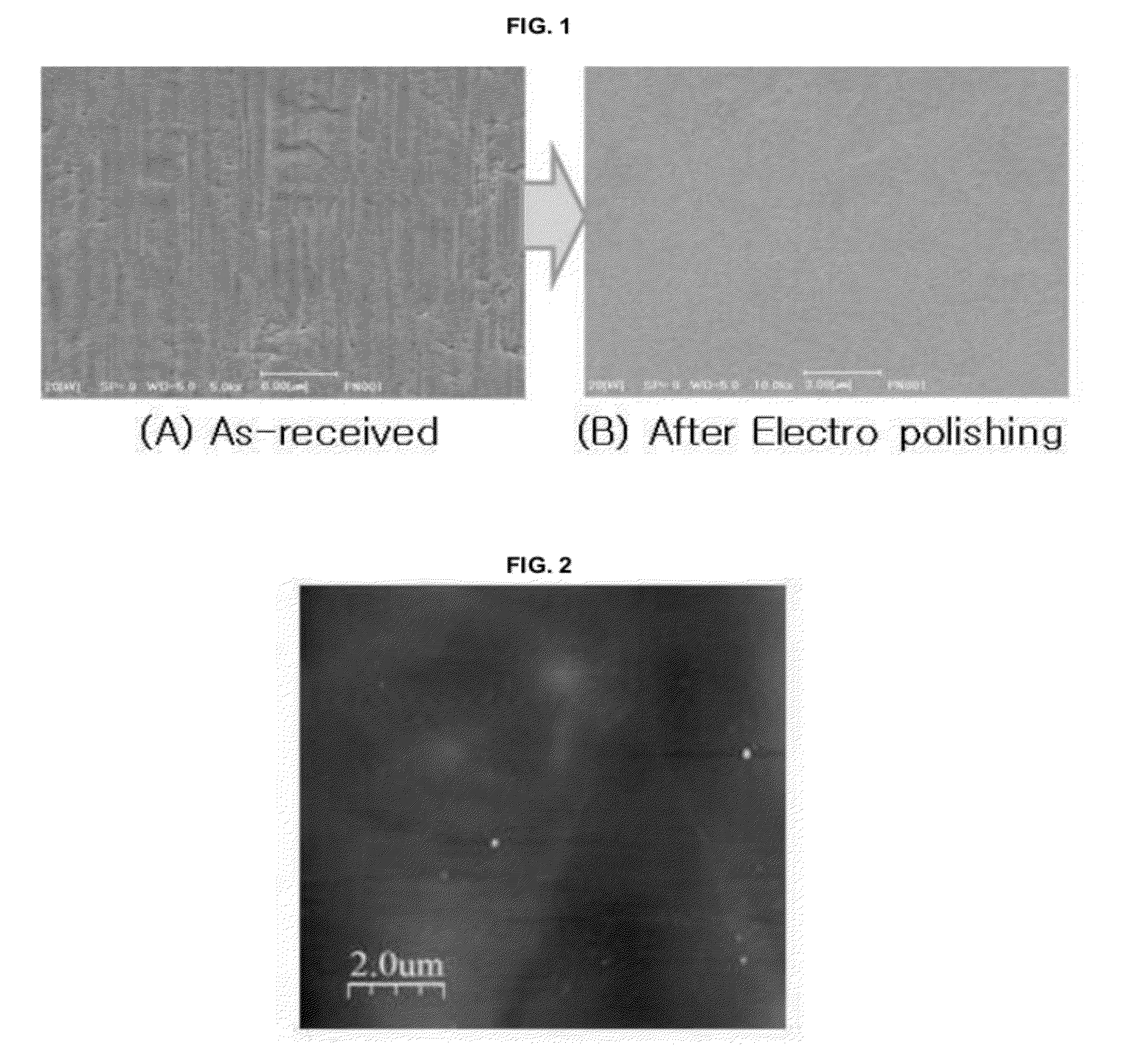
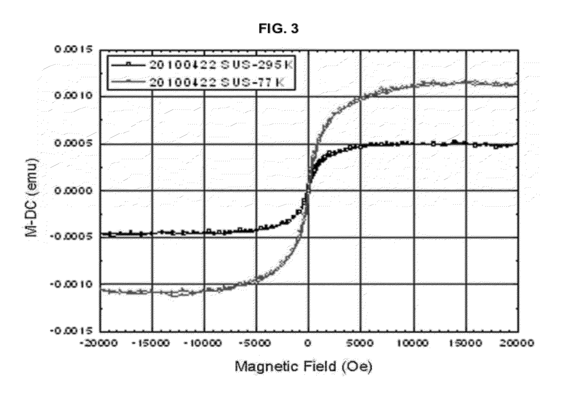
[0021]In this case, the substrate exhibits nonmagnetic properties and is inexpensive compared to a conventional hastelloy substrate, and is easily electropolished compared to a conventional stainless steel substrate, so that the surface roughness thereof is low and thus the thickness of a buffer layer can be reduced, with the result that a high-grade superconducting layer can be deposited on the thin buffer layer and thus the critical current density of th...


PUM


Abstract

Disclosed herein is a high-temperature superconducting tape, including: a substrate; a buffer layer formed on the substrate; and a high-temperature superconducting layer formed on the buffer layer, wherein the substrate is made of SUS310s or stainless steel containing 0.01-1% of silicon (Si) and 1-5% of molybdenum (Mo) and has an average metal crystal grain size of 12 μm or less, and the high-temperature superconducting layer is made of a ReBCO (ReBa2Cu3O7, Re=Nd, Sm, Eu, Gd, Dy, Ho, Y)-based superconductive material. The high-temperature superconducting tape is advantageous with the result that a high-grade superconducting layer can be deposited on the thin buffer layer and thus the critical current density of the high-temperature superconducting tape can be improved, thereby remarkably improving the characteristics of the high-temperature superconducting tape.

Description

REFERENCE TO RELATED APPLICATIONS[0001]This application claims the priority benefit of Korean Patent Application No. 10-2011-0029468 filed on Mar. 31, 2011, the entire contents of which are incorporated herein by reference.FIELD OF THE INVENTION[0002]The present invention relates to a high-temperature superconducting tape, and, more particularly, to a high-temperature superconducting tape, the critical current characteristics of which are improved because a stainless steel substrate, which is advantageous to electropolishing, is used and because of adjusting the composition ratio and crystal grain size of the stainless steel substrate.BACKGROUND OF THE INVENTION[0003]Generally, a high-temperature superconducting tape is manufactured by depositing a superconducting layer, such as YBCO, on a flexible metal substrate. When metal components of the metal substrate are diffused into the YBCO superconducting layer at high temperature (deposition temperature of YBCO) during the depositing p...

Claims


Application Information

Patent Timeline
IPC IPC(8): H01B12/02
CPCH01L39/2461H01L39/2454H10N60/0576H10N60/0632H01B12/06
Inventor HA, HONG SOOOH, SANG SOOKIM, HO SUP
Owner KOREA ELECTROTECH RES INST
Why Eureka
Try Eureka