System and method for clock generation with an output fractional frequency divider

a fractional frequency divider and clock signal technology, applied in the field of digital circuits, can solve the problems of vco, vco, and limited performance of pll b>101/b>, and achieve the effect of reducing complexity, and reducing the number of clock signals

Active Publication Date: 2017-07-04
ANALOG DEVICES INT UNLTD
View PDF4 Cites 1 Cited by
  • Summary
  • Abstract
  • Description
  • Claims
  • Application Information

AI Technical Summary

Problems solved by technology

The performance of PLL 101 is often limited by its VCO.
This is because a VCO that operates at a high absolute operating frequency or that operates over a wide frequency range, generally has a lower performance and a greater complexity than VCOs that operate at lower frequencies or over a narrower range.

Method used


Image

  • System and method for clock generation with an output fractional frequency divider
  • System and method for clock generation with an output fractional frequency divider
  • System and method for clock generation with an output fractional frequency divider

Examples


Embodiment Construction

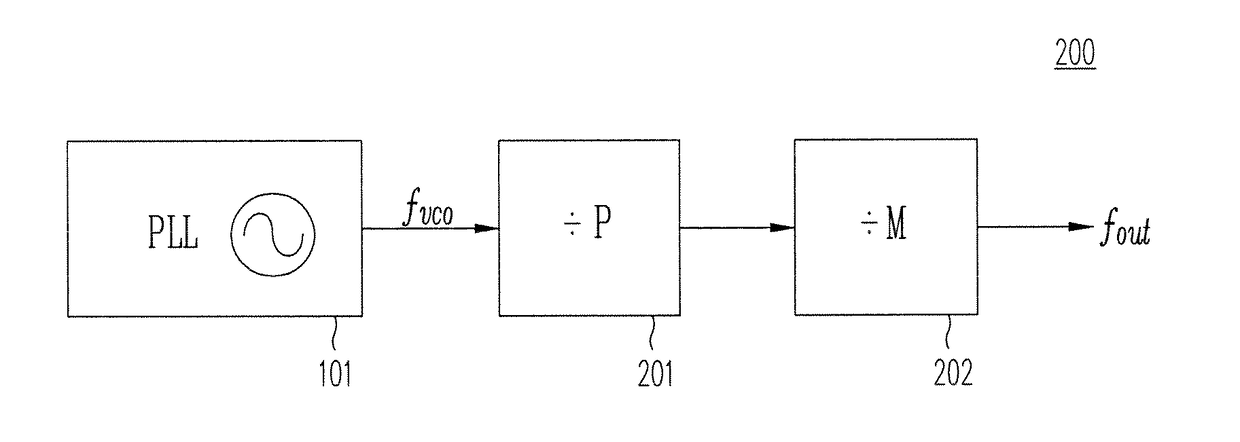
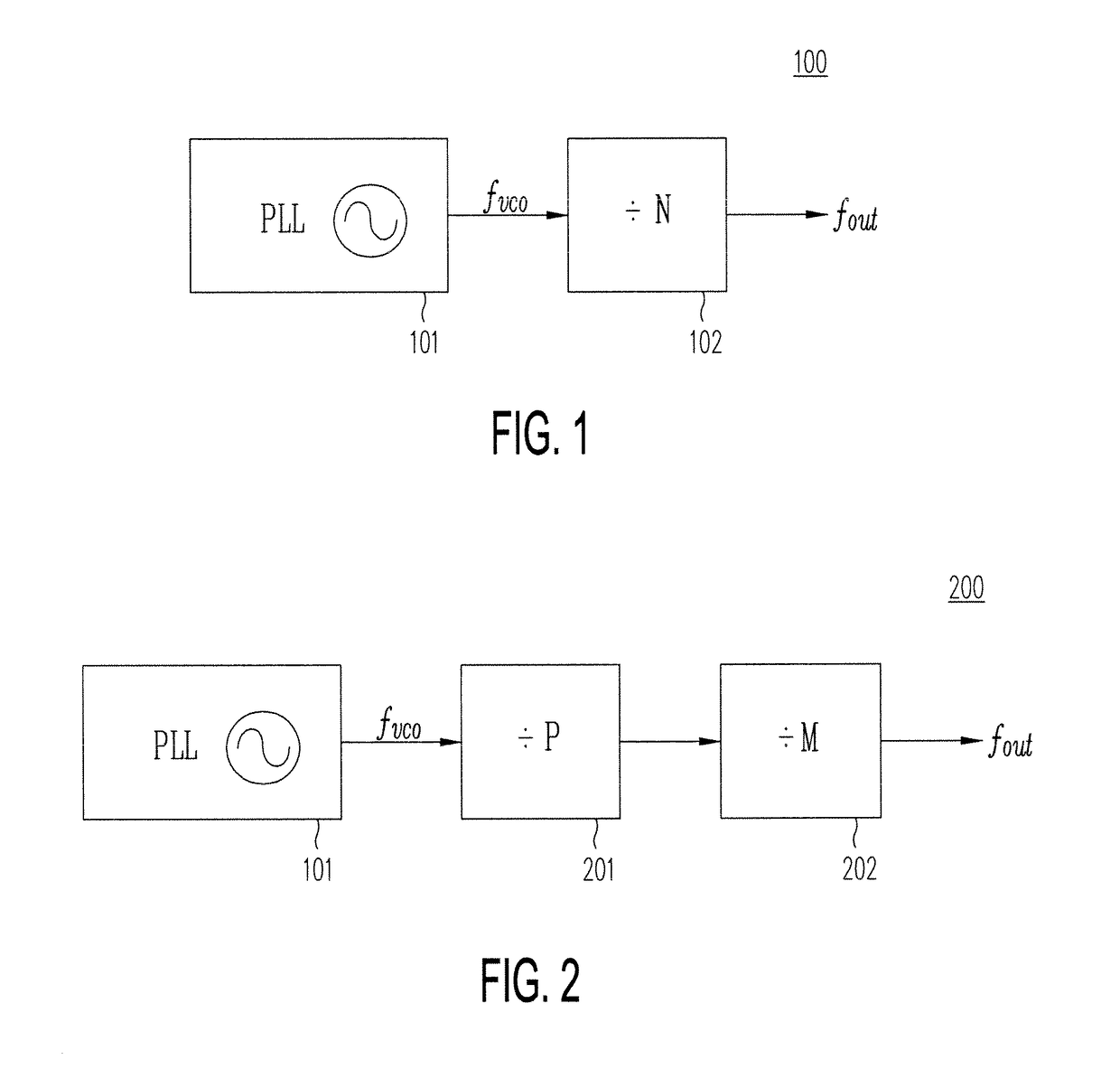
[0015]The present invention provides a clock generation circuit capable of generating an output clock signal that is a fractional submultiple of a source frequency. (In this detailed description, the term “fractional submultiple frequency” refers the frequency obtained by dividing a source frequency by an improper fraction). One example of a clock generation circuit of the present invention includes a clock signal divider circuit that allows frequency division in half-integer steps (e.g., a clock signal divider that allows frequency division by 1, 1.5, 2, 2.5, 3, 3.5, . . . ).

[0016]Using half-integer steps is advantageous over using full-integer steps. For example, if the required maximum operating frequency fmax of an output clock signal is 2.5 GHz, and the optimum maximum VCO frequency for a given process is 5 GHz, the least divider for a clock signal generation circuit manufactured using that process would be Nmin=2. In a prior art clock signal generation circuit, the next divide...


PUM


Abstract

A system and a method generate clock signals using an output divider with modulus steps of half-integers (i.e., the output circuit includes a divider which divides by one or more of 2, 2.5, 3, 3.5, 4 . . . ).

Description

CROSS REFERENCE TO RELATED APPLICATIONS[0001]The present application is related to and claims priority of U.S. provisional patent application (“Copending Provisional Application”), Ser. No. 62 / 030,486, entitled “System and Method for Clock Generation with an Output Fractional Frequency Divider,” filed on Jul. 29, 2014. The disclosure of the Copending Provisional Application is hereby incorporated by reference in its entirety.BACKGROUND OF THE INVENTION[0002]1. Field of the Invention[0003]The present invention relates to digital circuits. In particular, the present invention relates to clock signal generation circuits.[0004]2. Discussion of the Related Art[0005]In a typical prior art clock signal generation circuit, the output circuit includes a frequency divider that has integer modulus steps (i.e., the output clock signal is derived from dividing the frequency of a source clock signal, such as an internal clock signal, by an integer). In other words, the output signal has a frequen...

Claims


Application Information

Patent Timeline
Patent Type & Authority Patents(United States)
IPC IPC(8): H03L7/16H03K23/48H03K21/10
CPCH03L7/16H03K21/10H03K23/486
Inventor STEVENSON, JAN-MICHAEL
Owner ANALOG DEVICES INT UNLTD
Why Eureka
Try Eureka