
Axial transfer line shell side degassing

a transfer line and shell technology, applied in liquid degasification, liquid degasification by filtration, separation processes, etc., can solve the problems of chromatographic detector noise and drift, interference with the functionality or accuracy of application, and erroneous absorption signatures at the detector, so as to facilitate efficient and replicative shell-side degassing

Active Publication Date: 2017-07-11
IDEX HEALTH & SCI
View PDF27 Cites 7 Cited by
  • Summary
  • Abstract
  • Description
  • Claims
  • Application Information

AI Technical Summary

Benefits of technology

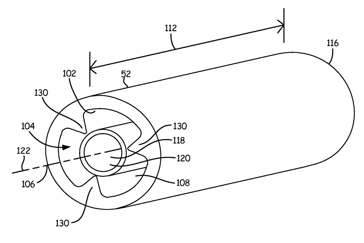
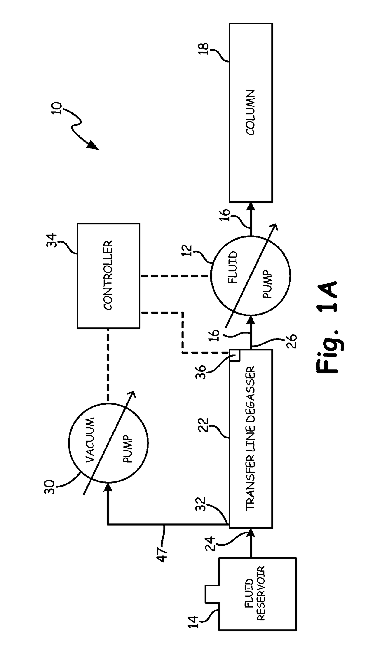
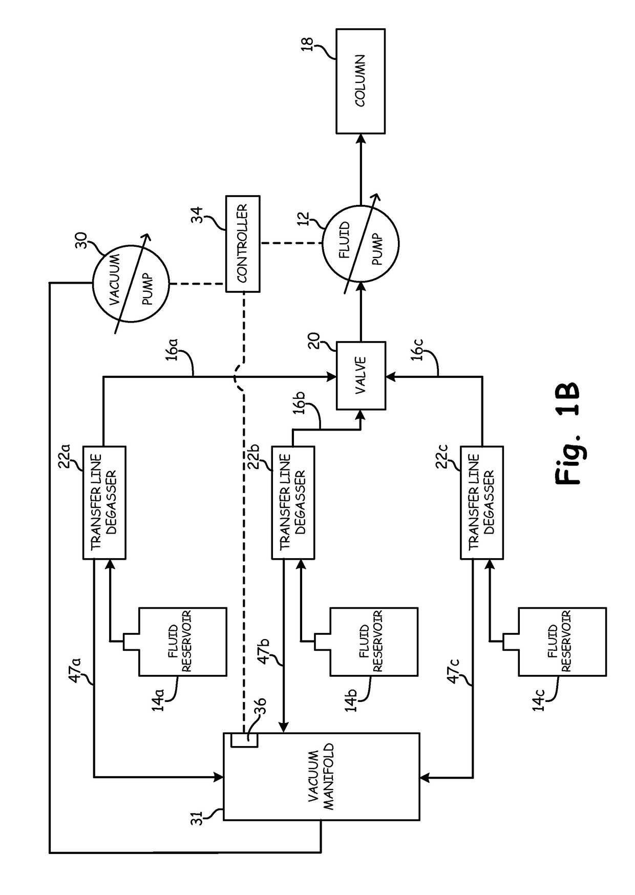
[0008]By means of the present invention, liquidous fluid may be operably degassed in distinct transfer lines extending between respective components in an associated fluid flow system. The transfer lines of the present invention may be configured as axially-disposed individual degassing units having an elongated outer jacket and one or more tubular separation membranes disposed in a chamber defined by the outer jacket. The tubular separation membrane is preferably physically supported in a manner to maintain the membrane in a spaced relationship from an inner surface of the outer jacket, with a radial gap defined radially between the membrane and the inner surface of the jacket. By supporting the one or more tubular separation membranes in a spaced relationship form the inner surface of the outer jacket, efficient and replicative shell-side degassing is facilitated through consistent liquid flow space about the one or more separation tubes.
[0009]Support provided externally to the tubular separation membrane may further facilitate a reduced membrane wall thickness for reduced cost of materials and potentially increased degassing performance.

Problems solved by technology

The presence of dissolved gasses can be undesirable in such applications, wherein the presence of dissolved gasses may interfere with the functionality or accuracy of the application.
Dissolved gasses in the mobile phase can manifest in the form of bubbles, which can cause noise and drift in the chromatographic detector.
Moreover, the existence of gas bubbles can cause erroneous absorption signatures at the detector.
While such transfer line degassing systems have proven to be somewhat effective, certain limitations are inherent with conventional design.
Such bending of the transfer line may result in the inner tubular separation membrane deflecting away from the central axis of the transfer line, and even into contact with the outer jacket.
Such displacement of the tubular membrane can disrupt fluid flow patterns, thereby diminishing gas transfer efficiency.
Degassing capability and efficiency in such an arrangement is limited, and is inferior to a “shell-side” degassing approach, wherein the liquidous fluid is passed through the chamber in surrounding relationship to the tubular separation membrane, with a reduced pressure or sweep gas environment presented in the lumen of the tubular separation membrane.

Method used


Image

  • Axial transfer line shell side degassing
  • Axial transfer line shell side degassing
  • Axial transfer line shell side degassing

Examples


Embodiment Construction

[0026]The objects and advantages enumerated above together with other objects, features, and advances represented by the present invention will now be presented in terms of detailed embodiments described with reference to the attached drawing figures, which are intended to be representative of various possible configurations of the invention. Other embodiments and aspects of the invention are recognized of being within the grasp of those having ordinary skill in the art.

[0027]A fluid degassing device as described herein includes an outer barrier that defines an interior chamber, wherein a substantially tubular separation membrane is positioned to separate the chamber into a permeate side and a retentate side. The retentate side of the chamber is configured for fluid-membrane contact along a fluid flow path between an inlet and an outlet of the apparatus. A degassing environment may be established at the permeate side of the chamber to develop a driving force for target gas to be tra...


PUM

PropertyMeasurementUnit
aspect ratioaaaaaaaaaa

Abstract

An elongated fluid degassing apparatus may be employed as a fluid transfer line for fluidly connecting components in a liquid system, while at the same time degassing, or preventing re-gassing of, the fluid. The fluid transfer line degassing apparatus forms a shell and tube degassing arrangement, wherein shell-side fluid flow is facilitated by one or more spacer elements that centrally position a semi-permeable separation membrane in the shell chamber. The degasser may include one or more tubular separation membranes that provide a gas-permeable, liquid-impermeable contact surface to effect the gas-liquid separation of the process fluid.

Description

CROSS-REFERENCE TO RELATED APPLICATIONS[0001]This application claims priority to U.S. Provisional Patent Application Ser. No. 62 / 069,426, filed on Oct. 28, 2014 and entitled “Axial Transfer Line Shell Side Degassing”, the content of which being incorporated herein in its entirety.BACKGROUND OF THE INVENTION[0002]The removal of entrained gasses from liquid is an important exercise in a variety of manufacturing and / or analytical processes. An example process in which liquid degassing is widely utilized is in liquid chromatography applications. The presence of dissolved gasses can be undesirable in such applications, wherein the presence of dissolved gasses may interfere with the functionality or accuracy of the application.[0003]In the case of liquid chromatography, for example, it has long been known that the reduction of dissolved air from the chromatographic mobile phase is of critical importance to the stability of system flow rate and, accordingly, to the proper identification of...

Claims


Application Information

Patent Timeline
Patent Type & Authority Patents(United States)
IPC IPC(8): B01D19/00B01D69/04
CPCB01D19/0031B01D69/046B01D69/04
Inventor LIU, QUANGERNER, YURISIMS, CARL
Owner IDEX HEALTH & SCI
Learn More