
Gearbox shift lock

a technology of gearbox and shift lock, which is applied in the direction of fluid actuated clutches, non-mechanical actuated clutches, gearing elements, etc., can solve the problems of premature damage, untimely disengagement of the clutch of the gearbox, and excessive wear and tear, so as to prevent inadvertent disengagement of the clutch

Active Publication Date: 2017-07-11
CJ LUX HLDG S A R L +1
View PDF8 Cites 0 Cited by
  • Summary
  • Abstract
  • Description
  • Claims
  • Application Information

AI Technical Summary

Benefits of technology

The invention is an apparatus and method that prevents the clutch from disengaging accidentally in a vehicle during operation. This can be caused by a reduction in fluid pressure in the clutch circuit. By using the invention, it prevents premature destruction of the gearbox and ensures safe shifting of the gear at high speeds.

Problems solved by technology

However, normal service conditions of conventional systems often cause excessive wear and tear.
For example, if the fluid pressure supplied to maintain engagement between the clutch and the gearbox reduces below a certain threshold during operation, the clutch of the gearbox can disengage in an untimely fashion and become prematurely damaged.

Method used


Image

  • Gearbox shift lock
  • Gearbox shift lock
  • Gearbox shift lock

Examples


Embodiment Construction

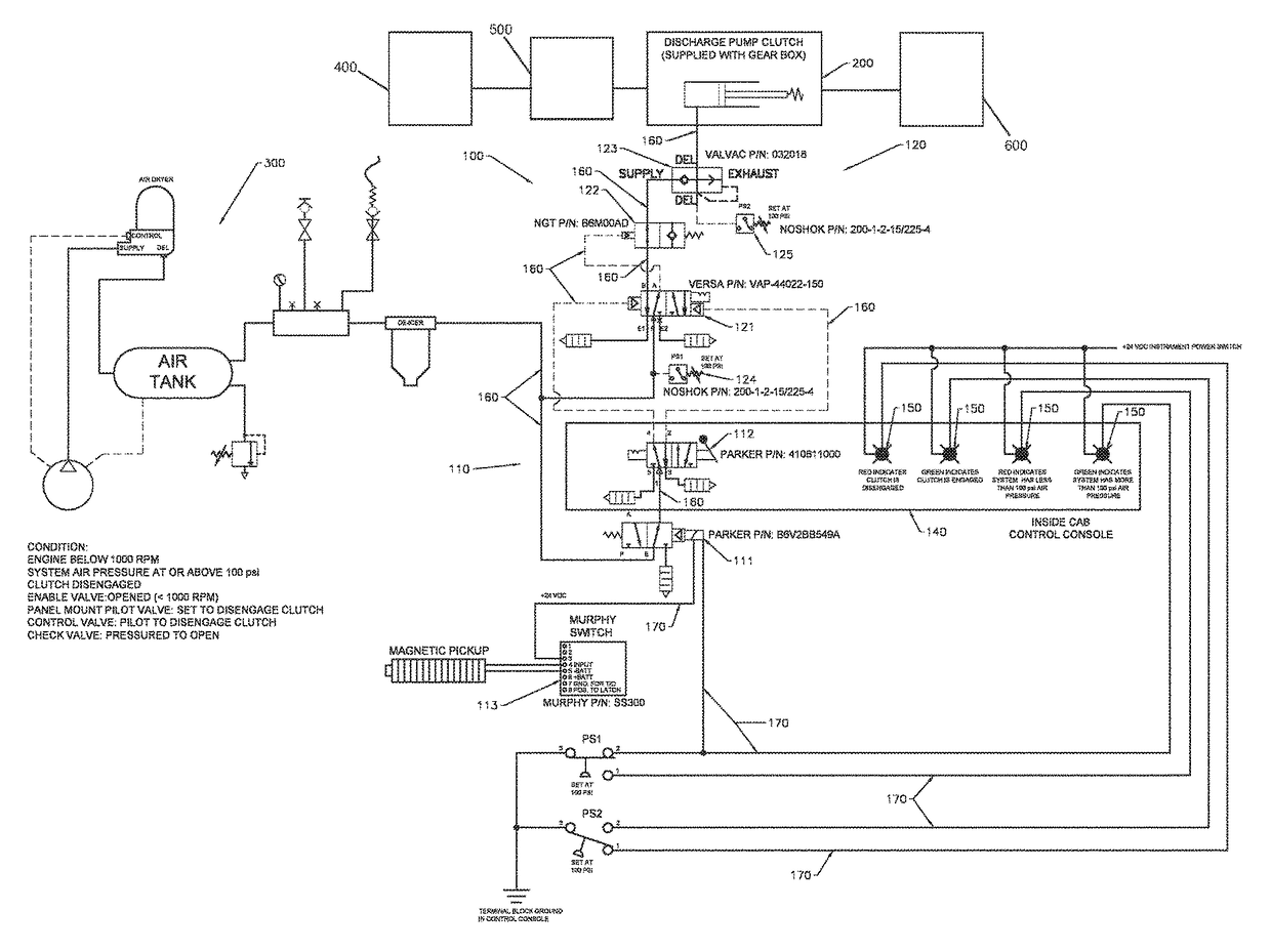
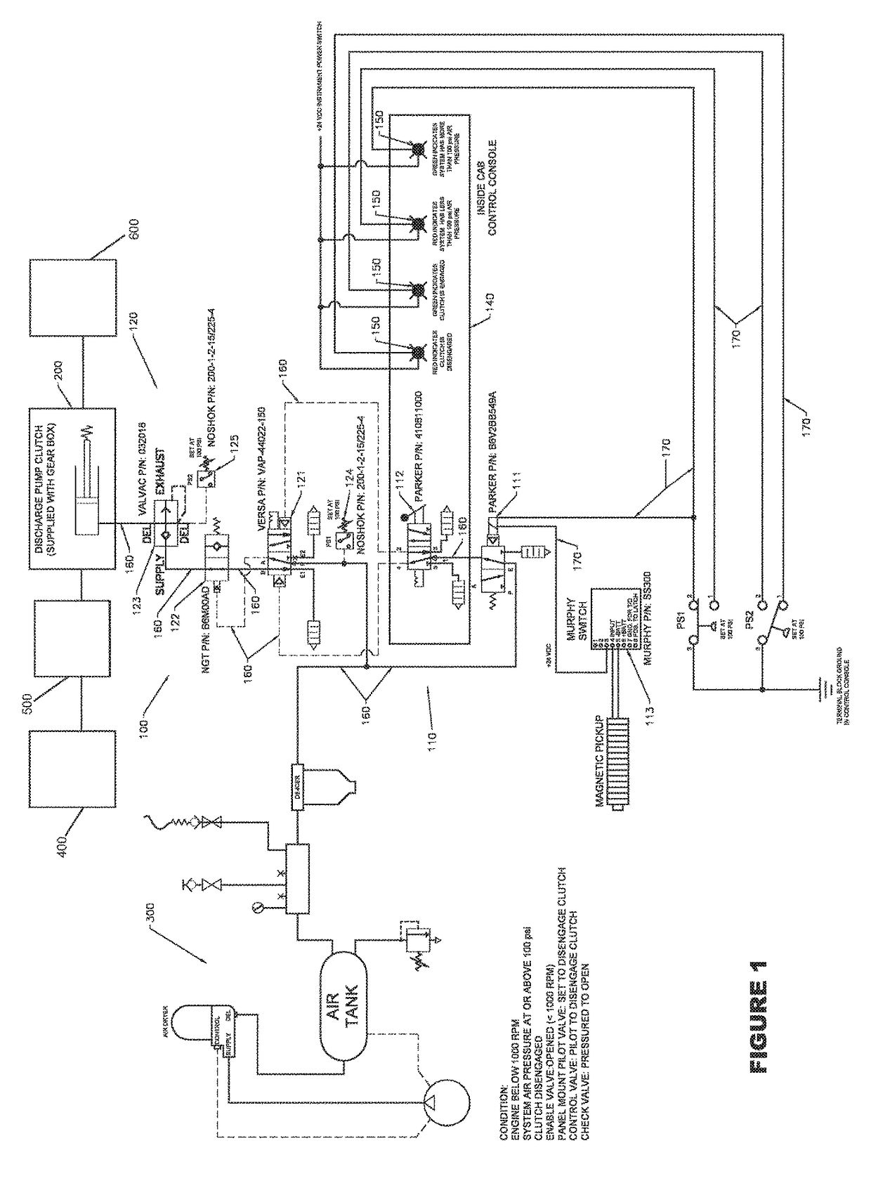
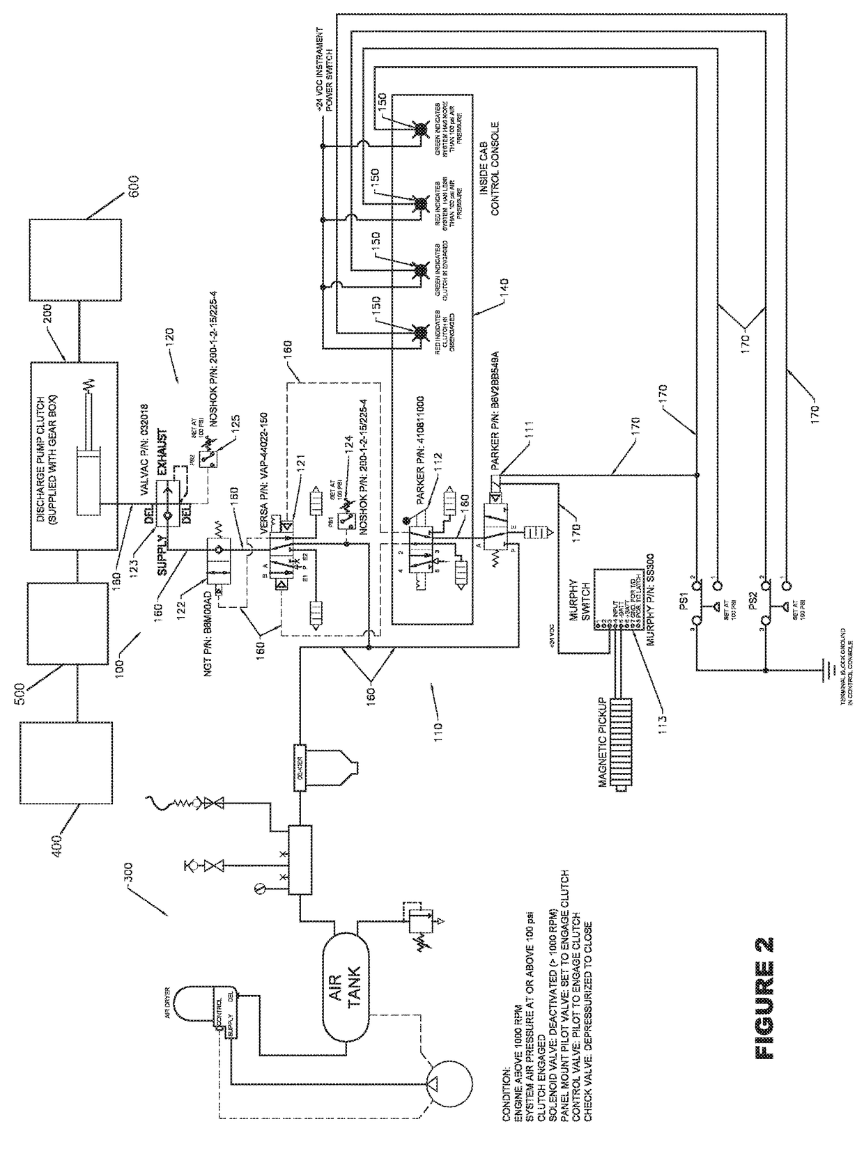
[0019]Without any intent to limit the scope of this invention, reference is made to the figures in describing various embodiments of the invention. FIGS. 1-4 illustrate various embodiments of a fluid powered circuit 100 for a gearbox 400 in accordance with this invention. The gearbox 400 has a shaft 500 that is actuated by a motor 600 through a clutch 200, and can have a spring loaded clutch cylinder. The clutch 200 can be moved to either an engaged or disengaged position using fluid pressure (e.g., pneumatic, hydraulic, etc.) For example, the clutch 200 can be pneumatically operated by flowing a fluid from a fluid supply source 300 (e.g., an air compressor) through the fluid powered circuit 100. An example of a suitable gearbox including a clutch for use with this invention includes, but is not limited to, a reduction gearbox (Model No. GR1600E), which is available from Cotta™ Transmission Company, LLC of Beloit, Wis.

[0020]The fluid powered circuit 100 is selectively operable to ei...


PUM


Abstract

A fluid powered circuit for a gearbox and a method for protecting a gearbox are disclosed. The fluid powered circuit includes a control circuit operatively connected to a clutch engagement circuit. The fluid powered circuit is selectively operable to either flow a fluid from a fluid supply source to the clutch or vent the fluid to the atmosphere. The method for protecting the gearbox includes flowing the fluid from the fluid supply source to the fluid powered circuit, measuring the speed of the shaft, measuring the pressure of the fluid entering the clutch engagement circuit, and flowing the fluid from the fluid powered circuit to the clutch upon detecting one or more conditions.

Description

BACKGROUND OF THE INVENTION[0001]Field of the Invention[0002]The present disclosure relates to apparatuses and systems for controlling the engagement and / or disengagement of a clutch using fluid pressure.[0003]Description of Related Art[0004]Gearboxes of various blenders and pumps, including for example, those used for slurry pumps, are typically shifted into gear using fluid pressure (e.g., pneumatic, hydraulic, etc.). However, normal service conditions of conventional systems often cause excessive wear and tear. For example, if the fluid pressure supplied to maintain engagement between the clutch and the gearbox reduces below a certain threshold during operation, the clutch of the gearbox can disengage in an untimely fashion and become prematurely damaged.[0005]Accordingly, there remains a need in the art for a fluid powered circuit that is capable of protecting a gearbox from damage due to reduction in fluid pressure.BRIEF SUMMARY OF THE INVENTION[0006]The invention meets the for...

Claims


Application Information

Patent Timeline
Patent Type & Authority Patents(United States)
IPC IPC(8): F16H59/38F16D25/12F16H63/30F16H59/72F16H61/00F16H61/02F16H59/68
CPCF16H61/0021F16H63/3023F16H59/72F16H59/38F16H61/0206F16H2059/683F16D25/12F16D2048/0263F16D2048/0266F16D48/02F16D2048/0278
Inventor RAGUSE, BENJAMIN LYLESCHMIDT, DANIEL BROOKSSHERWOOD, RONALD MARK
Owner CJ LUX HLDG S A R L
Learn More