Quick connect with male and female terminals

a technology of male and female terminals, applied in the direction of couplings, rod connections, manufacturing tools, etc., can solve the problems of adding to the cost and complexity of the connector assembly

Inactive Publication Date: 2011-04-19
REASONER MICHAEL V
View PDF21 Cites 17 Cited by
  • Summary
  • Abstract
  • Description
  • Claims
  • Application Information

AI Technical Summary

Benefits of technology

[0008]A linearly displaceable and sleeve shaped covering cap is supported upon the male terminal in a biasing direction towards the spherical shaped projecting portion. The covering cap is displaces in a first anti-biasing direction (such as toward an end of the male terminal opposite the spherical shaped projection), his providing clearance for the outward deflecting motion of the beams. Upon seating of the male projection into the female recessed profile and concurrent retraction of the spring loaded beams, the cap is released and its bias force displaces an open ended and annular shaped wall of the cap into a seating position over the projecting ends of the beams, thereby preventing inadvertent disengagement of the terminals under tension, compression or bending leads. Final seating position provides a zero free play joint.
[0010]The spherical enlarged shape is spaced a specified distance from a main body portion of the male terminal by a narrow diameter neck portion, the dimensions of which permit the tapered nose and spherical shape to be linearly and resistively engaged against the end defined fingers. An annular undercut portion is defined at a linear location associated with the male terminal main body and seating therein a first annular winding end associated with an assembleable coil spring. The spring so mounted biases and linearly displaces the cover cap in a lineal direction so that its open ended and inner facing annular seating surface coaxially overlays the end fingers associated with the deflectable beams, thus maintaining the seating engagement of the male enlarged shape within the female inner profile.

Problems solved by technology

A known problem associated with such quick connectors is the requirement for utilizing additional clips or fasteners for retaining together the male / female portions, this adding to both the cost and complexity of the connector assembly.

Method used


Image

  • Quick connect with male and female terminals
  • Quick connect with male and female terminals
  • Quick connect with male and female terminals

Examples


Embodiment Construction

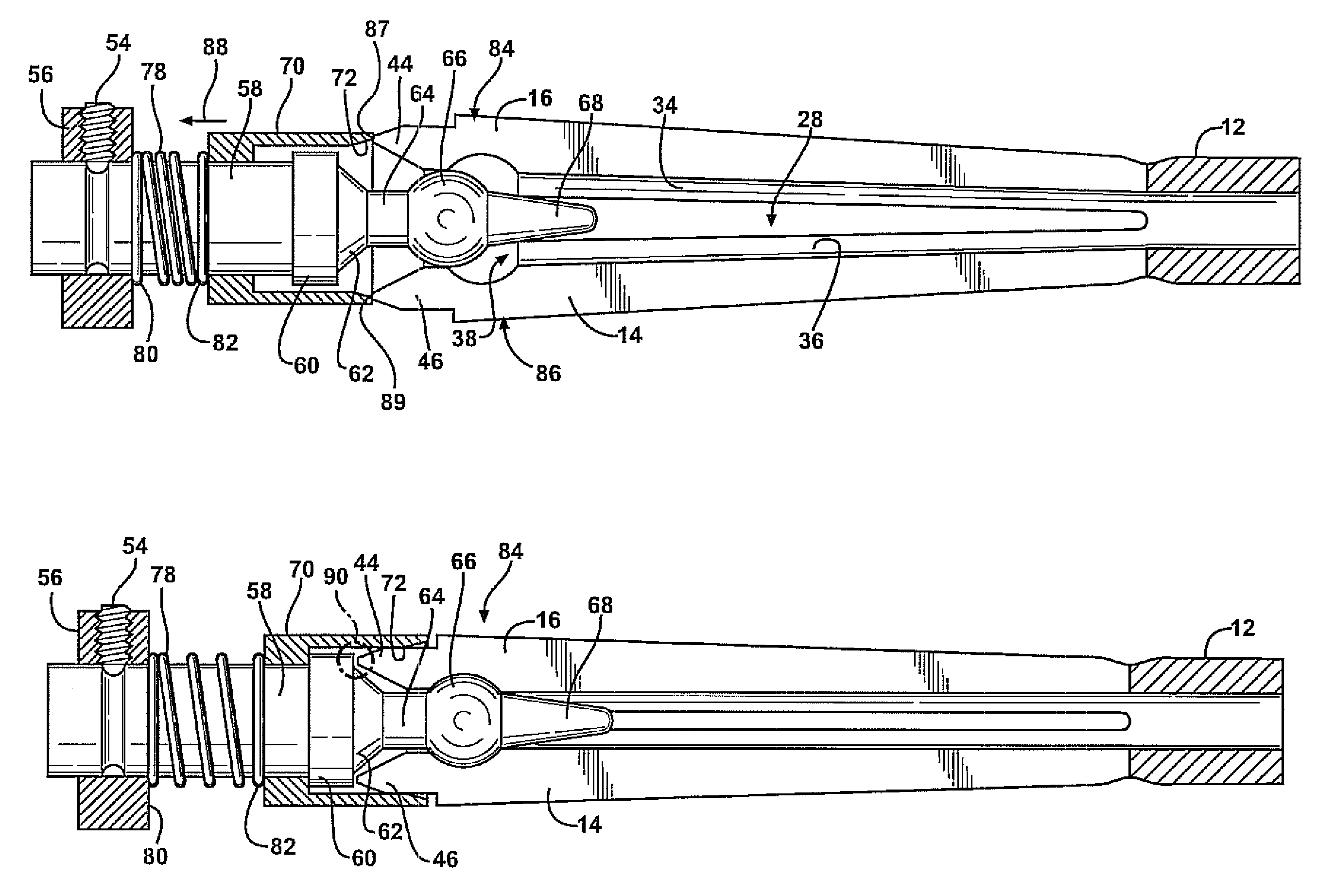
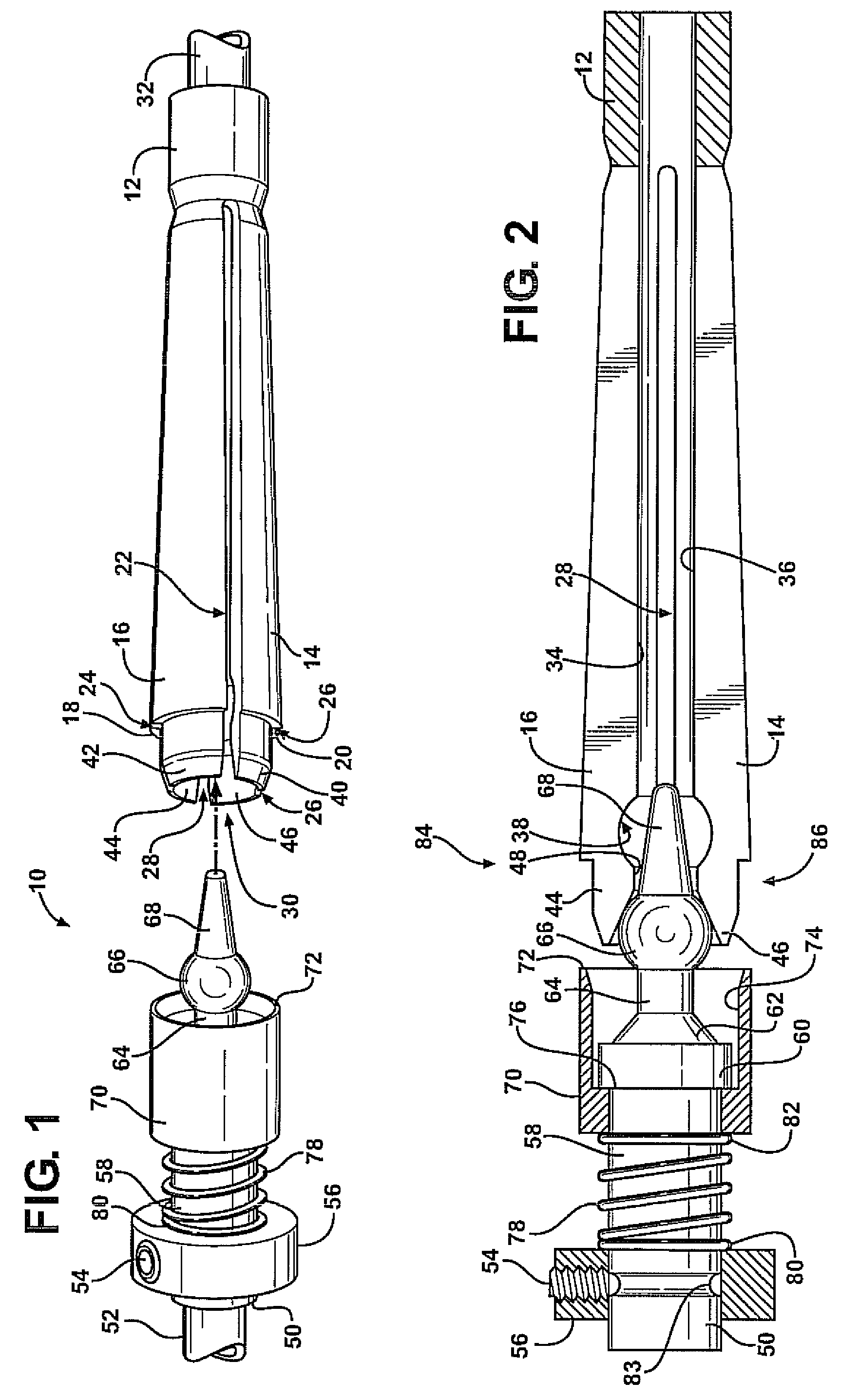
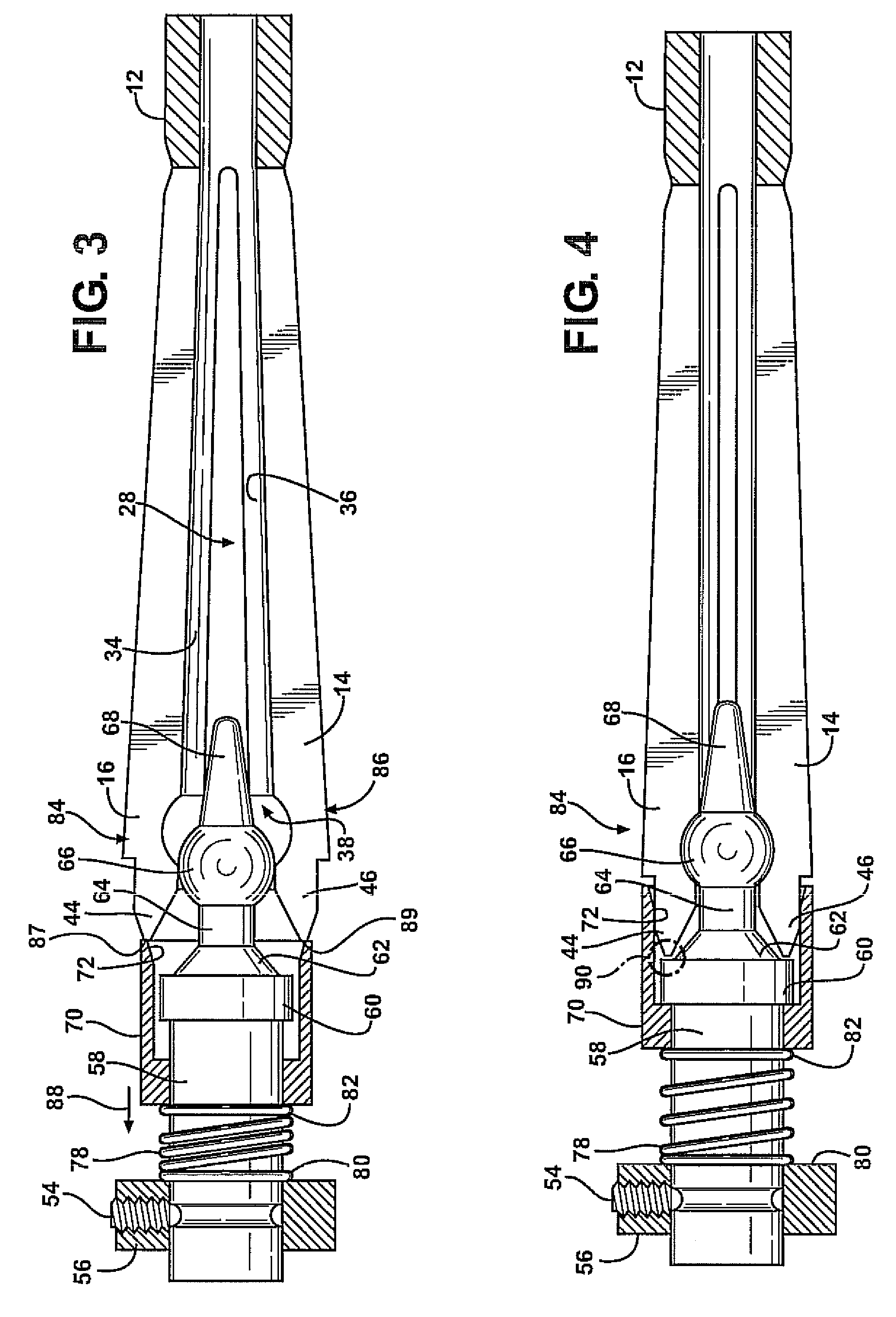
[0017]Referring now to each of FIGS. 1-4, an improved quick connect assembly is generally shown at 10 according to a first preferred embodiment. As previously described, the present invention provides a more efficient quick connect assembly with male and female connecting portions and which does not require the provision of additional clips or fasteners.

[0018]The connector assembly illustrates a female terminal which possesses a generally elongated body including a generally annular shaped end, see at 12, and from which extend a plurality of linear extending and spring biasing beams 14, 16, 18 and 20. The beams 14-20 collectively exhibit a generally elongated and three dimensional configuration.

[0019]The beams are constructed so that opposing and linear extending edges of each beam are spaced apart to render the beams deflectable and spring loaded. This is illustrated by the beams being spaced in a circumferential fashion, thereby establishing a like plurality of elongate and linear...


PUM


Abstract

A quick connect assembly having a female terminal exhibiting an interior passage communicating with a connecting end. The passage is defined by inwardly facing surfaces associated with a plurality of linearly extending and peripherally arrayed beams, the passage exhibiting an enlarged profile an inwardly recessed distance from the connecting end. A male terminal includes a projecting portion generally matching the enlarged profile. The male terminal is inserted into the female terminal, causing the beams to outwardly deflect, following which the beams inwardly retract concurrent with the projecting portion seating within the inner profile. A linearly displaceable and sleeve shaped covering cap is spring supported upon the male terminal and displaceable between a first anti-biased position permitting outward deflection of the beams and a second biased position seating over projecting ends of the beams to prevent inadvertent disengagement of the terminals.

Description

CROSS-REFERENCE TO RELATED APPLICATIONS[0001]The present application claims the priority of U.S. Provisional Patent Application Ser. No. 61 / 053,931 filed May 16, 2008.FIELD OF THE INVENTION[0002]The present invention discloses a quick connect assembly which functions without the requirement for clips and fasteners for retaining together first male and second female connector portions. Specific applications and features include such as rotate-ability, auto-locking serviceability, as well as tension and compression load bearing connection of any type including cable wire connections and the like, this optionally providing electrical connectivity / conductivity and in addition to mechanical applications which do not require electrical connection between the male and female terminals.BACKGROUND OF THE INVENTION[0003]Quick connect couplings are well known in the art, such as include first and second engageable members (these also including such as other known male and female or ball and so...

Claims


Application Information

Patent Timeline
Patent Type & Authority Patents(United States)
IPC IPC(8): F16B7/00
CPCF16G11/10Y10T403/1624Y10T403/5713Y10T403/581Y10T403/32254Y10T403/66Y10T403/32311F16B2200/69
Inventor REASONER, MICHAEL V.
Owner REASONER MICHAEL V
Why Eureka
Try Eureka