Replaceable ribbon supply and substrate cleaning apparatus

a cleaning apparatus and replacement technology, applied in typewriters, printing, instruments, etc., can solve the problems of losing the effectiveness of rolling machines, affecting the cleaning effect of debris, and most end users neglecting to change the sticky removal members, etc., to achieve a balanced insertion into the printer, the effect of ensuring the cleaning

Active Publication Date: 2011-05-03
ZEBRA TECH CORP
View PDF160 Cites 25 Cited by
  • Summary
  • Abstract
  • Description
  • Claims
  • Application Information

AI Technical Summary

Benefits of technology

[0011]The cartridge frame preferably includes one or more locating features that facilitate insertion of the ribbon cartridge into a printer. For example, the cartridge frame may define one or more detents that are shaped to receive corresponding reference protrusions extending from a printer frame. These detents may have a rounded portion and may be positioned approximately midway between the spools so as to facilitate a smooth, balanced insertion.
[0013]A cleaning roller may be connected to the frame of the ribbon cartridge by one or more springs. For example, the ribbon cartridge may include a pair of cantilevered springs that are attached on one end to the cartridge frame and extend outward to another end to support ends of the cleaning member. For the roller-type cleaning member, the ends of the cantilever springs may include a pair of cleaning roller supports configured to rotatably support ends of the cleaning member. To provide clearance for deflection of the cleaning roller, the ribbon cartridge may define a pair of cantilever cutouts in its sidewalls. Advantageously, this provides for easy assembly of the cleaning roller and the cartridge frame at the time of its manufacture.
[0015]The present invention includes many advantages. For example, the various locating features, such as the rounded detent with its positioning between the spools, provides for easy, balanced insertion into the printer. The tag pocket provides for more secure positioning of somewhat delicate smart card chips.

Problems solved by technology

It will be evident that as the tacky surface of the cleaning roller accumulates debris the roller will lose its effectiveness so that the cleaning roller itself needs to be kept clean.
It has been found, however, that most end users neglect to change the sticky removal member when it loses its debris-lifting effectiveness.
As a result, debris remaining on the substrate surface can enter the print mechanism causing poor print quality and ultimately leading to the destruction of the printhead that is the most expensive component of the printer.

Method used


Image

  • Replaceable ribbon supply and substrate cleaning apparatus
  • Replaceable ribbon supply and substrate cleaning apparatus
  • Replaceable ribbon supply and substrate cleaning apparatus

Examples


Embodiment Construction

[0036]The present invention now will be described more fully hereinafter with reference to the accompanying drawings, in which some, but not all embodiments of the invention are shown. Indeed, the present invention may be embodied in many different forms and should not be construed as limited to the embodiments set forth herein; rather, these embodiments are provided so that this disclosure will satisfy applicable legal requirements. Like numbers refer to like elements throughout.

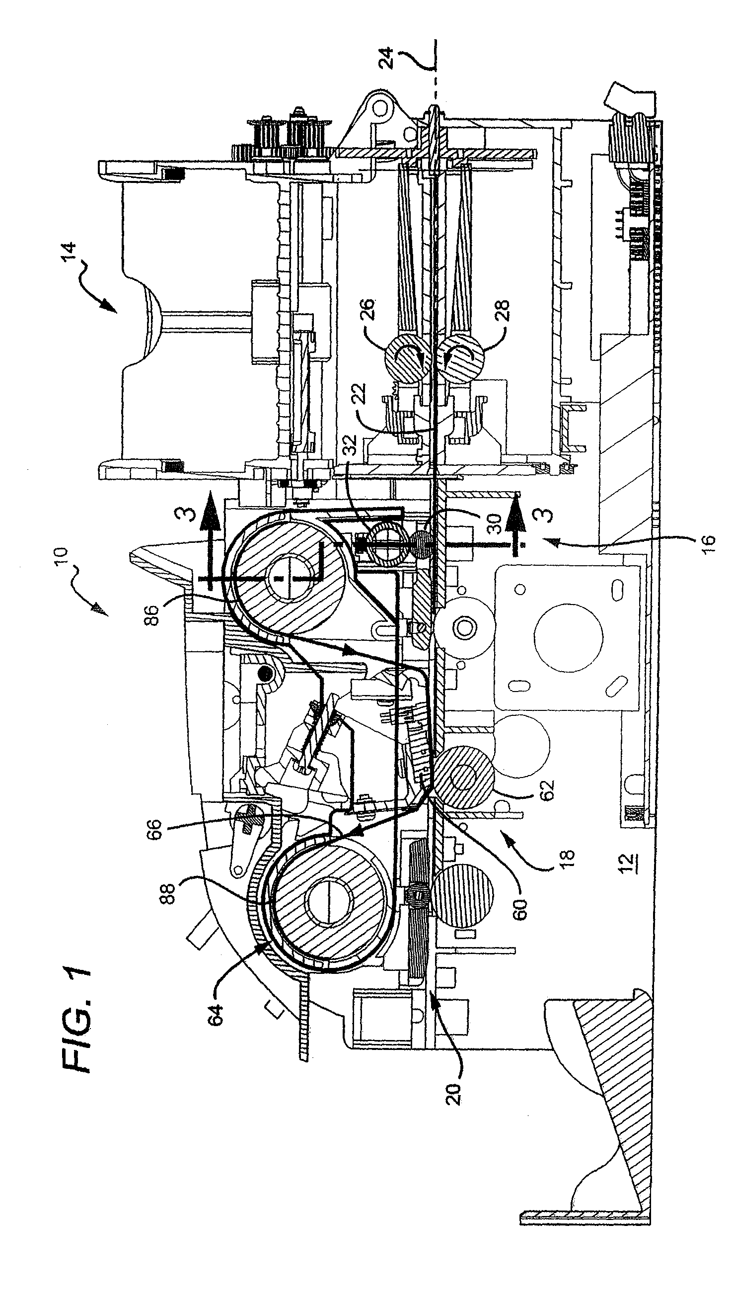
[0037]With reference to FIG. 1, there is shown a portion of a thermal transfer printer 10 incorporating a specific, exemplary embodiment of the present invention. As is known, thermal transfer printers are typically used to print information in the form of text, graphics, photographs, and so forth, on plastic cards such as I.D. cards, drivers' licenses, and the like using a printer consumable such as a thermal transfer or dye sublimation ribbon-carried by a disposable ribbon cartridge. It will be evident to...


PUM


Abstract

A ribbon cartridge for a printer. The ribbon cartridge includes a frame that supports supply and take-up spools and that has one or more locating features to facilitate its insertion and positioning in a frame of a printer. For example, the ribbon cartridge frame may include a pair of detents defined approximately midway between the two spools to facilitate balanced insertion. The detents are slots with rounded ends that are configured to receive similarly shaped reference protrusions of the printer frame. The cartridge frame may also define a pocket for receiving an identification tag associated with the ribbon cartridge that ensures compatibility with the printer and passage of other information to the printer. In other embodiments, the ribbon cartridge may include a cleaning roller.

Description

CROSS-REFERENCES TO RELATED APPLICATIONS[0001]This application claims priority to U.S. Provisional Application Ser. No. 60 / 672,642, filed Apr. 19, 2005, and to copending U.S. patent application Ser. No. 10 / 690,395, filed on Oct. 20, 2003, both of which are hereby incorporated herein in their entirety by reference.FIELD OF THE INVENTION[0002]The present invention relates generally to printers for printing on discrete, flexible, information-bearing substrates such as plastic cards, and particularly to an apparatus receivable in a printer that is self-locating and accurately positions interfacing components used in printing on the substrates and removing particulate matter such as dust and / or other debris from the substrates.BACKGROUND OF THE INVENTION[0003]Printers for printing information on discrete, flexible substrates such as plastic identification cards, drivers licenses, prepaid cards, and the like, conventionally comprise a substrate hopper and feeder for storing and supplying ...

Claims


Application Information

Patent Timeline
Patent Type & Authority Patents(United States)
IPC IPC(8): B41J32/00B41J17/32
CPCB41J3/50B41J3/60B41J17/32B41J13/12B41J11/0035
Inventor LODWIG, DEAN H.BRYANT, CALEB J.CHAVARRIA, LIONEL C.PERRY, DANIEL E.
Owner ZEBRA TECH CORP
Why Eureka
Try Eureka