
Equilibrium-point prosthetic and orthotic ankle-foot systems and devices

a technology of orthotic ankle and prosthetics, applied in the field of improved prosthetic systems, can solve the problems problems that can arise, and many currently available prosthetic and orthotic ankle-foot mechanisms that do not allow ankle motion, so as to prevent or reduce the likelihood of compromising user's balan

Active Publication Date: 2013-12-03
U S GOVERNMENT REPRESENTED BY THE DEPT OF VETERANS AFFAIRS +1
View PDF23 Cites 29 Cited by
  • Summary
  • Abstract
  • Description
  • Claims
  • Application Information

AI Technical Summary

Benefits of technology

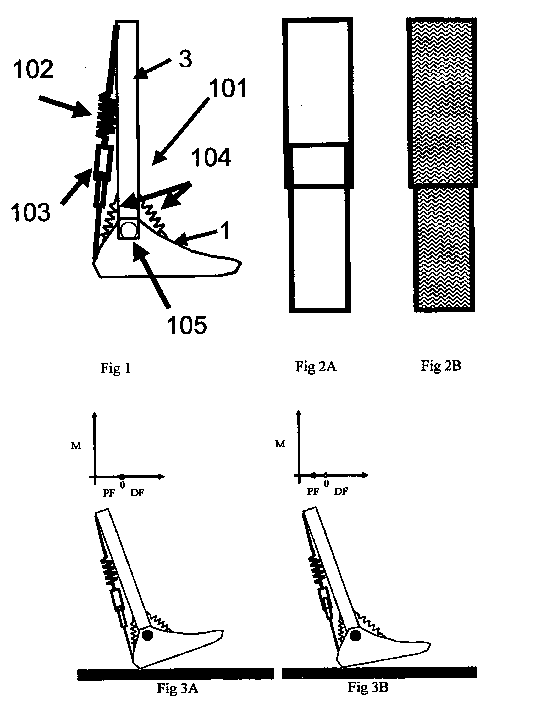
This invention is a prosthetic and orthotic ankle-foot device that can help users walk more confidently and comfortably. It automatically adapts to different surface inclinations and shoes, and mimics the natural movement of the ankle-foot system. The device also reduces energy requirements for individuals using it, which can help users walk faster and more confidently.

Problems solved by technology

Many currently available prosthetic and orthotic ankle-foot mechanisms do not allow ankle motion.
However, problems can arise when walking on different terrain or when using shoes of different heel height.
However, this is not a simple task and one that does not happen automatically.
However, Koniuk's design does not appear to have energy storage and release properties, utilizes more sensing devices than the proposed design, and does not appear to give plantarflexion at late stance.
Current prosthetic ankle-foot mechanisms cannot automatically adapt to these conditions.
Many currently available prosthetic and orthotic ankle-foot mechanisms do not allow ankle motion.
However, problems can arise when walking on different terrain or when using shoes of different heel height.
However, this is not a simple task and one that does not happen automatically.

Method used


Image

  • Equilibrium-point prosthetic and orthotic ankle-foot systems and devices
  • Equilibrium-point prosthetic and orthotic ankle-foot systems and devices
  • Equilibrium-point prosthetic and orthotic ankle-foot systems and devices

Examples


example i

Use of Weight-Activation to Control the Ankle Mechanism

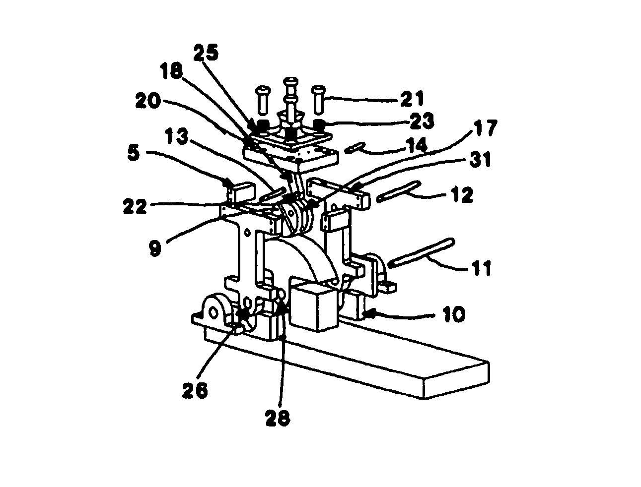
[0134]Engagement can be set to occur upon loading of the device by the user's weight. In this case, a mechanism is in place that engages the triceps surae torsional means after a sufficient amount of body weight has been applied to the system. Upon unloading of the device, the engagement reverses (that is the triceps surae spring is disengaged from the rest of the system). Examples of this type of engagement are shown in devices #2 and #3.

example ii

Use of Potentiometers or Encoders to Control Locking-Unlocking Mechanisms

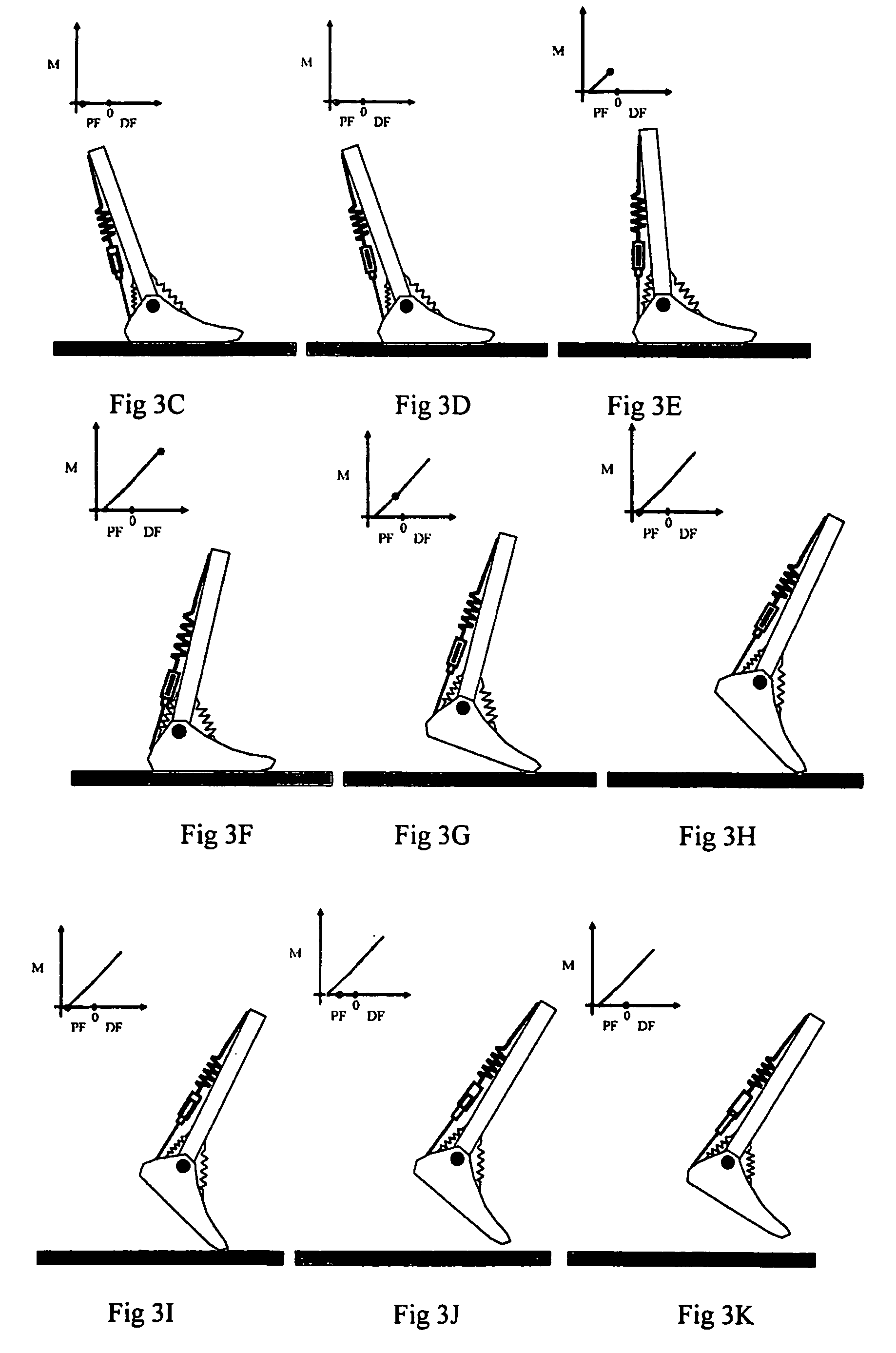
[0135]The projected ankle motion of this device is shown in FIG. 33. The potentiometers or encoders measure these angles during use of the device. In early stance, the locking mechanism may be unlocked. When the rotational sensor indicated that a minimum dorsiflexion angle is reached (at time 1), the system will signal to engage the locking mechanism. This mechanism remains engaged until this angle is approached at the end of stance phase (at time 2), at which time the system unlocks and allows the neutralizing springs to bring the ankle back to neutral for swing phase.

example iii

Use of Forefoot Pressure Sensors to Control Locking-Unlocking Mechanisms

[0136]An alternative way to control the locking and unlocking mechanism is to use a forefoot pressure sensor. In early stance, the ankle plantarflexes until the forefoot contacts the walking surface. At this first contact with the forefoot pressure sensor, the locking mechanism may be engaged. Forefoot contact remains until the toe comes off of the ground at the end of stance. At this time, the pressure goes to zero and the locking mechanism could be unlocked, allowing the neutralizing springs to bring the ankle back to neutral for swing phase.


PUM


Abstract

The present invention relates to a system for use in rehabilitation and / or physical therapy for the treatment of injury or disease. The system can enable an amputee to proceed over any surface without overbalancing. In particular the system is self-adapting to adjust the torque moment depending upon the motion, the extent of inclination, and the surface topography.

Description

CROSS-REFERENCE TO RELATED APPLICATIONS[0001]The present application claims priority to International Patent Application Number PCT / US07 / 22208 entitled “Equilibrium-Point Prosthetic and Orthotic Ankle-Foot Systems, Devices, and Methods of Use”, filed Oct. 17, 2007, which in turn claimed priority to U.S. Provisional Patent Application Ser. No. 60 / 852,174 entitled “Equilibrium-Point Prosthetic and Orthotic Ankle-Foot Devices”, filed Oct. 17, 2006, both which are herein incorporated by reference in their entirety for all purposes.STATEMENT REGARDING FEDERALLY SPONSORED RESEARCH OR DEVELOPMENT[0002]This invention was made with government support under H133E030030 awarded by the National Institute on Disability and Rehabilitation Research (United States Department of Education). The United States government has certain rights in the invention.TECHNICAL FIELD[0003]The inventions relates to improved prosthetic systems and methods of use. In particular the prosthesic systems comprise an ank...

Claims


Application Information

Patent Timeline
Patent Type & Authority Patents(United States)
IPC IPC(8): A61F2/66
CPCA61F2/6607A61F2/68A61F2002/5003A61F2002/5009A61F2002/5036A61F2002/5072A61F2002/6818A61F2002/6845A61F2002/6854A61F2002/701A61F2002/704A61F2002/7625A61F2002/7635A61F2002/7645A61F2/70
Inventor HANSEN, ANDREW H.GARD, STEVEN A.CHILDRESS, DUDLEY S.RUHE, BRIANWILLIAMS, RYAN
Owner U S GOVERNMENT REPRESENTED BY THE DEPT OF VETERANS AFFAIRS
Learn More