
Electro-optical device comprising first, second, and third color beams having different incident angles relative to a light gathering element and electronic apparatus

a technology of optical transmission device and light gathering element, which is applied in the direction of static indicating device, picture reproducer using projection device, instrument, etc., can solve the problems of risk of mixing the second color beam and the third color beam with each other, and the risk of worsening display darkness, so as to reduce the risk of color mixture, reduce the width l1, and the effect of sufficient optical transmission

Active Publication Date: 2017-07-11
SEIKO EPSON CORP
View PDF24 Cites 0 Cited by
  • Summary
  • Abstract
  • Description
  • Claims
  • Application Information

AI Technical Summary

Benefits of technology

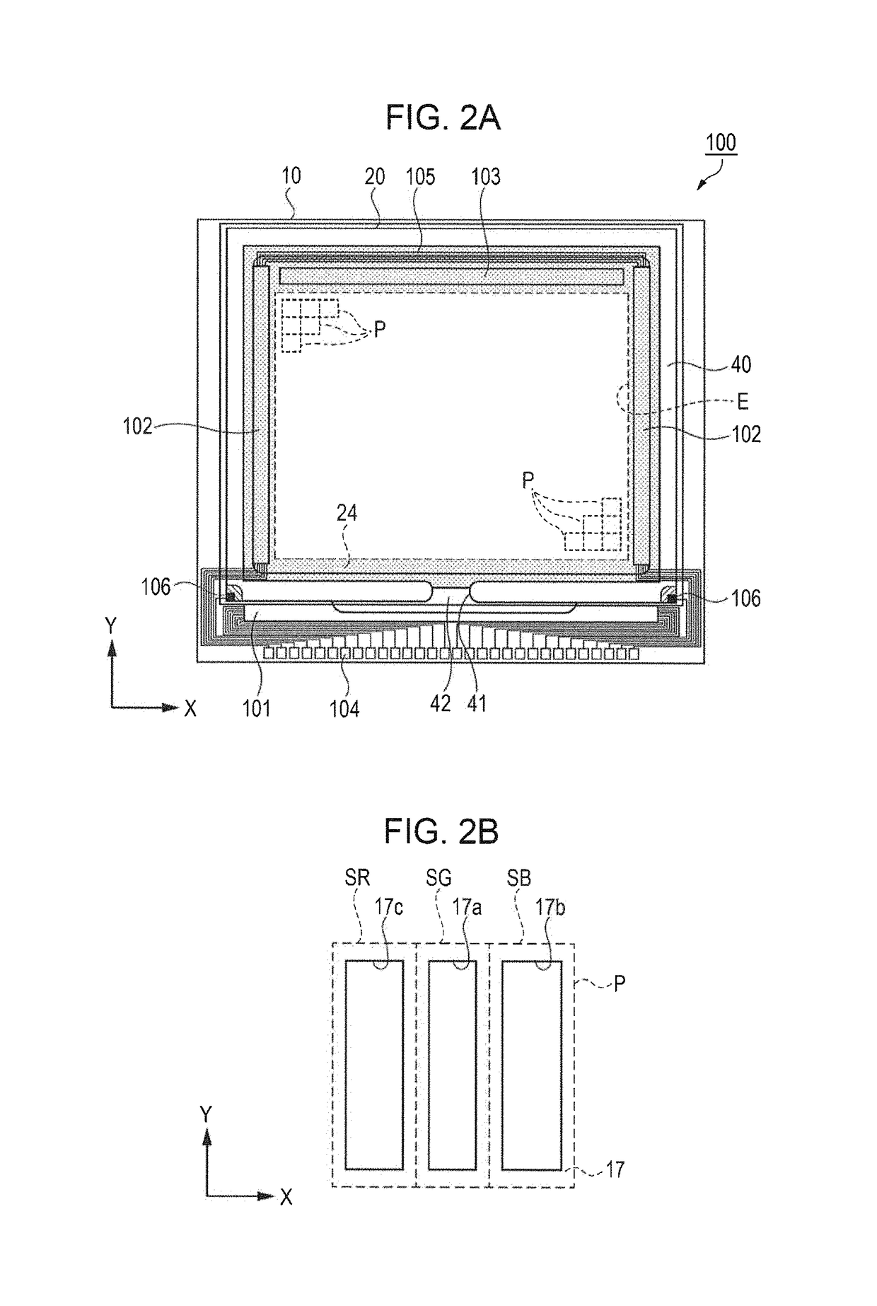
[0010]In this application example, at the second opening portion located adjacent to the first opening portion in the predetermined direction, though the second color beam enters the second opening portion in an oblique direction with respect to the normal-line direction, the transmittance of the second color beam passing through the second opening portion is less likely to decrease because the width L2 of the second opening portion is greater than the width L1 of the first opening portion. For the same reason as that for the second opening portion, at the third opening portion located adjacent to the first opening portion in the predetermined direction, the transmittance of the third color beam passing through the third opening portion is less likely to decrease. Since the greater width makes optical transmittance at the second opening portion or the third opening portion harder to decrease than that at the first opening portion, it is possible to provide an electro-optical device that is capable of performing bright color display without using any color filter. Moreover, since the greater width makes optical transmittance at the second opening portion or the third opening portion harder to decrease than that at the first opening portion, even if the transmittance at each sub pixel is adjusted for the purpose of white-balance display adjustment, it is possible to perform bright color display.
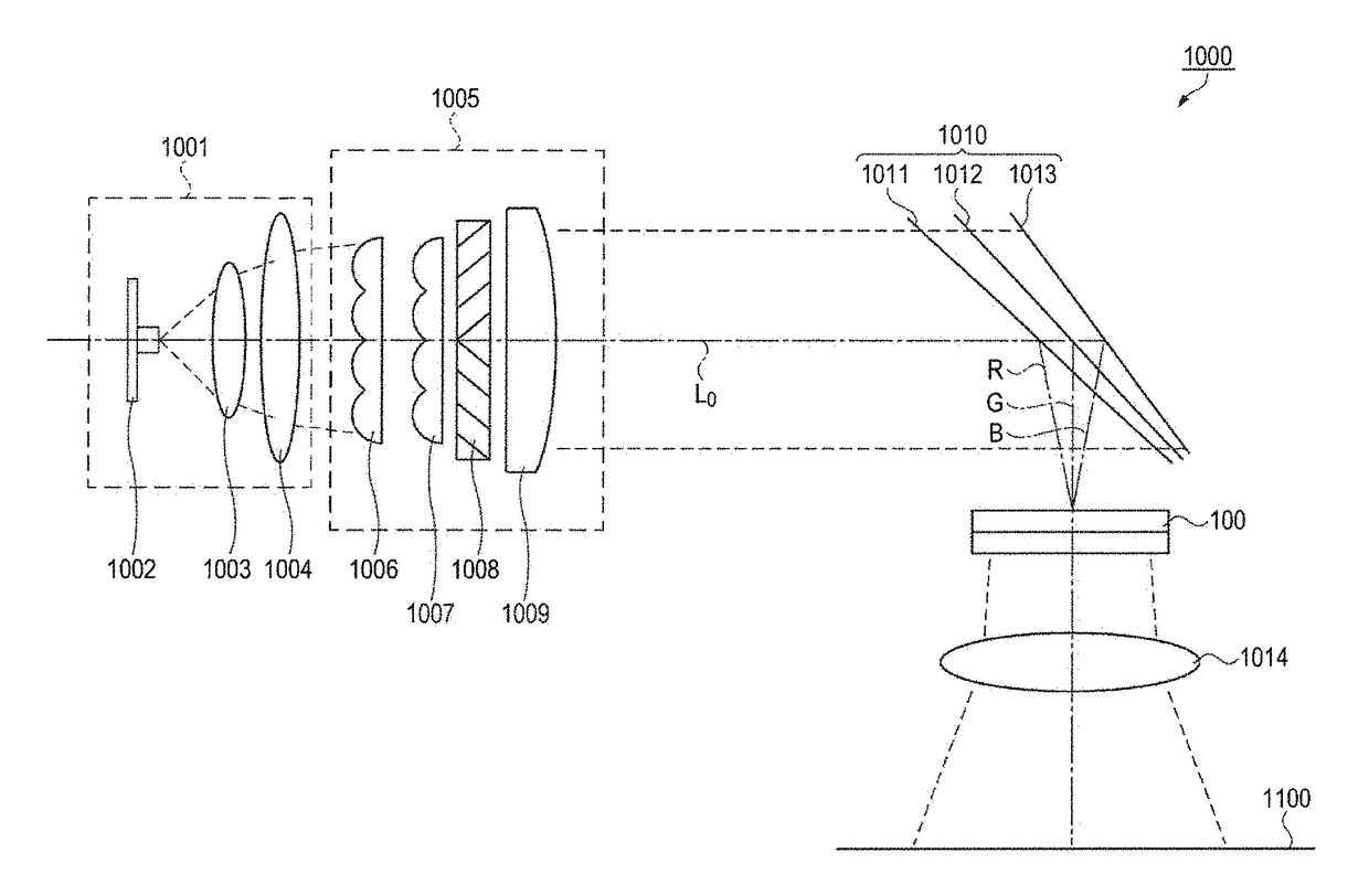
[0016]An electronic apparatus according to this application example comprises: the electro-optical device according to the above application example; the light source; and a color separation element that splits the light emitted from the light source into the first, second, and third color beams, the wavelengths of which are different from one another. With this application example, it is possible to provide an electronic apparatus that is capable of performing bright and beautiful color display.

Problems solved by technology

Moreover, there is a risk of the mixture of the second color beam and the third color beam with each other.
Furthermore, if actual optical transmittance at other pixel opening portions is adjusted for the purpose of white-balance display adjustment while taking, as the reference for the adjustment, the optical transmittance at the second pixel opening portions or the third pixel opening portions, which is lower than that at the first pixel opening portions, there is a risk of worsened display darkness.

Method used


Image

  • Electro-optical device comprising first, second, and third color beams having different incident angles relative to a light gathering element and electronic apparatus
  • Electro-optical device comprising first, second, and third color beams having different incident angles relative to a light gathering element and electronic apparatus
  • Electro-optical device comprising first, second, and third color beams having different incident angles relative to a light gathering element and electronic apparatus

Examples


second embodiment

[0092]Next, with reference to FIGS. 11 to 14, an electro-optical device according to a second embodiment will now be explained. FIG. 11 is a schematic sectional view of the structure of a pixel in a liquid crystal device according to a second embodiment. FIG. 12 is a graph that shows a relationship between the wavelength of light and the index of refraction of a micro lens. FIG. 13 is a graph that shows a relationship between a distance from a micro lens array to opening portions and transmittance at the opening portions. FIG. 14 is a plan view of the arrangement of sub pixels in a pixel according to the second embodiment.

[0093]The difference between a liquid crystal device 200, which is an electro-optical device according to the second embodiment, and the liquid crystal device 100 of the first embodiment lies in, firstly, the way as to how color beams enter a pixel P (micro lens ML), and, secondly, the structure of sub pixels SR, SG, and SB corresponding thereto. Therefore, the sam...

first modification example

[0109]The electro-optical device functioning as an optical modulator is not limited to a liquid crystal device. For example, the invention may be applied to a transmissive-type MEMS (Micro Electro Mechanical System) display.

second modification example

[0110]The electronic apparatus to which the liquid crystal device 100 of the first embodiment is applied is not limited to the projection-type display device 1000. For example, it can be suitably used as an optical modulator for an HUD (Head Up Display) or an HMD (Head Mount display). The same holds true for the liquid crystal device 200 of the second embodiment.


PUM

PropertyMeasurementUnit
frequencyaaaaaaaaaa
lengthaaaaaaaaaa
radiusaaaaaaaaaa

Abstract

As an electro-optical device, a liquid crystal device includes micro lenses ML each of which is provided as a light-gathering element for the corresponding one of pixels, and further includes a light-shielding portion. Red (R), green (G), and blue (B) beams enter the micro lens ML at angles different from one another. The light-shielding portion partitions off a first opening portion corresponding to a sub pixel, a second opening portion corresponding to a sub pixel, and a third opening portion corresponding to a sub pixel from one another. When the width of the first opening portion in the predetermined direction (X direction) is defined as L1 and when the width of the second opening portion or the third opening portion in the predetermined direction is defined as L2, a relationship of L1<L2 holds true.

Description

BACKGROUND[0001]1. Technical Field[0002]The present invention relates to an electro-optical device and an electronic apparatus.[0003]2. Related Art[0004]As an example of an electro-optical device, an image display device disclosed in JP-A-2005-010382 is known. This image display device has a plurality of pixels each of which has first, second, and third pixel opening portions. A beam of light emitted from a light source is split into first, second, and third color beams, the wavelength regions of which are different from one another. The first, second, and third color beams enter the first, second, and third pixel opening portions, respectively. In this image display device, the second pixel opening portions and the third pixel opening portions are arranged at a predetermined pitch (P) in a predetermined direction, with the first pixel opening portions centered therebetween. The center of the light-gathering spot of the first color beam is located inside the first pixel opening port...

Claims


Application Information

Patent Timeline
Patent Type & Authority Patents(United States)
IPC IPC(8): H04N9/31G02F1/1335G02B27/10
CPCG02B27/1053G02F1/133512G02F1/133621H04N9/3108G02F1/133526G02B3/0056G02B27/0905G02F1/133623G09G3/2003
Inventor NAKAMURA, NORIO
Owner SEIKO EPSON CORP
Learn More