Method of controlling a brushless motor

a brushless motor and motor control technology, applied in the direction of single-phase motor control, electronic commutator, synchronous motor starter, etc., can solve the problems of motor actual speed exceeding the upper threshold and/or dropping below the lower threshold, and achieves relatively small memory requirements, simple computation, and relatively large power and/or load tolerance.

Active Publication Date: 2017-07-11
DYSON TECH LTD
View PDF12 Cites 3 Cited by
  • Summary
  • Abstract
  • Description
  • Claims
  • Application Information

AI Technical Summary

Benefits of technology

[0009]The method is relatively simple to implement computationally, and the memory requirements are relatively small. Accordingly, the method may be implemented using a relatively simple and therefore cheap controller. Additionally, the method may be implemented without adversely affecting the execution of other routines.
[0014]The method may comprise rectifying an alternating voltage to provide a rectified voltage, exciting the phase winding with the rectified voltage, and obtaining the speed-adjusted control value in response to each zero-crossing of the alternating voltage. This then has the advantage that the speed-adjusted control value is updated at regular intervals without the need for a dedicated timer. Additionally, the speed-adjusted control value may be updated in synchrony with the cycle of the alternating voltage. As a result, the waveform of current drawn from the power supply providing the alternating voltage is generally more stable.

Problems solved by technology

However, for a mass-produced motor, tolerances in the motor and / or the load under which the motor operates may mean that actual speed of the motor exceeds the upper threshold and / or drops below the lower threshold.

Method used


Image

  • Method of controlling a brushless motor
  • Method of controlling a brushless motor
  • Method of controlling a brushless motor

Examples


Embodiment Construction

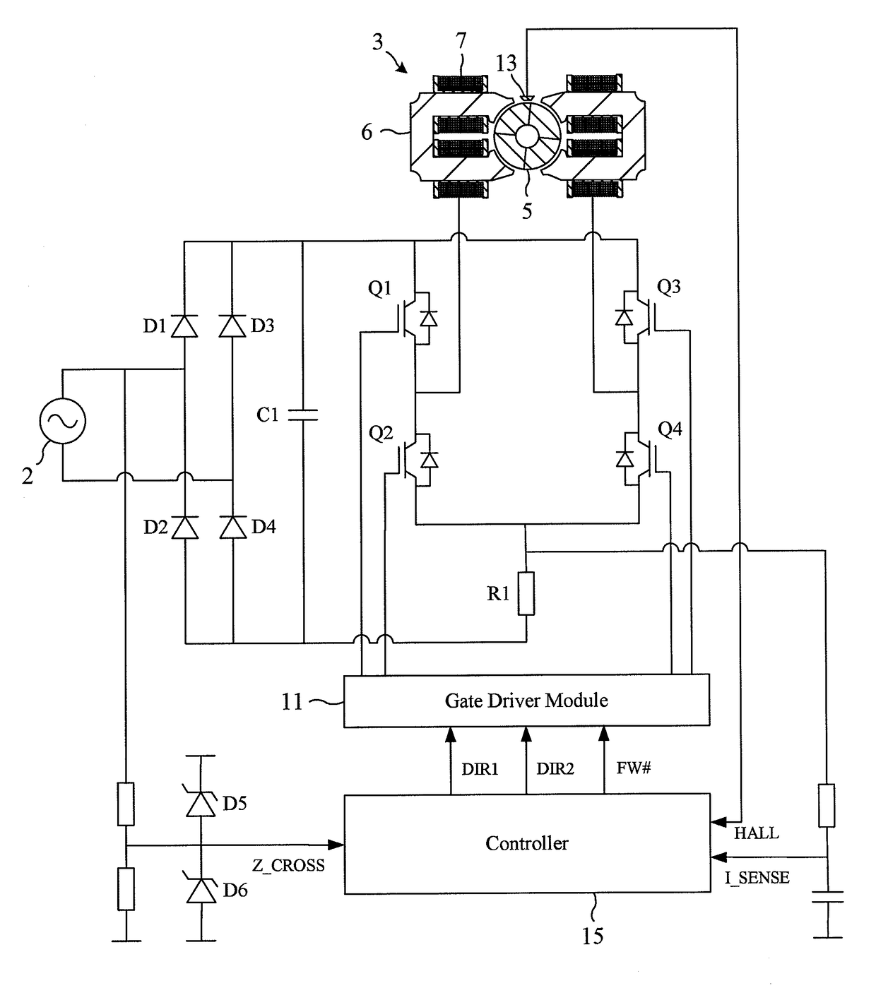
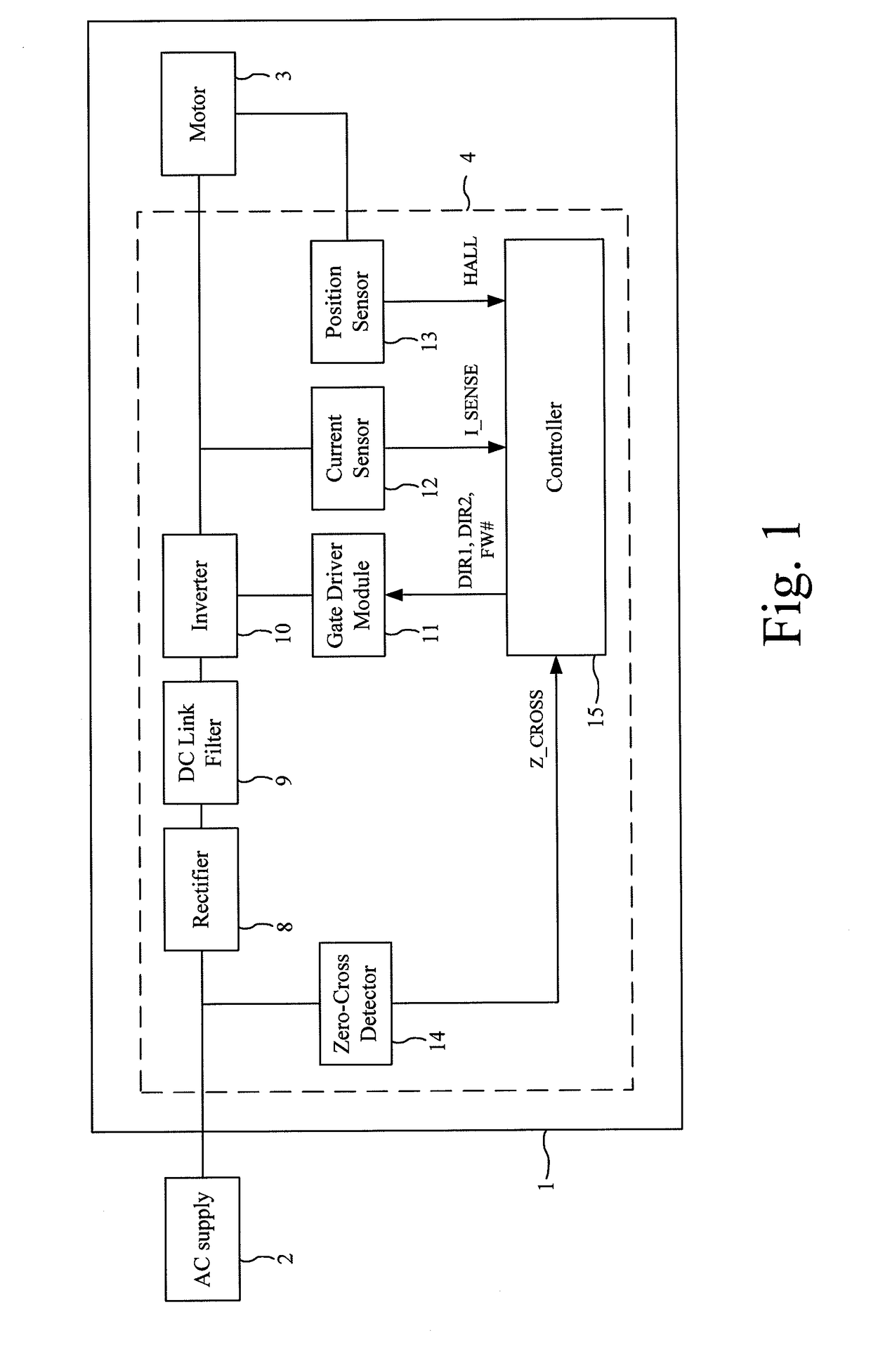
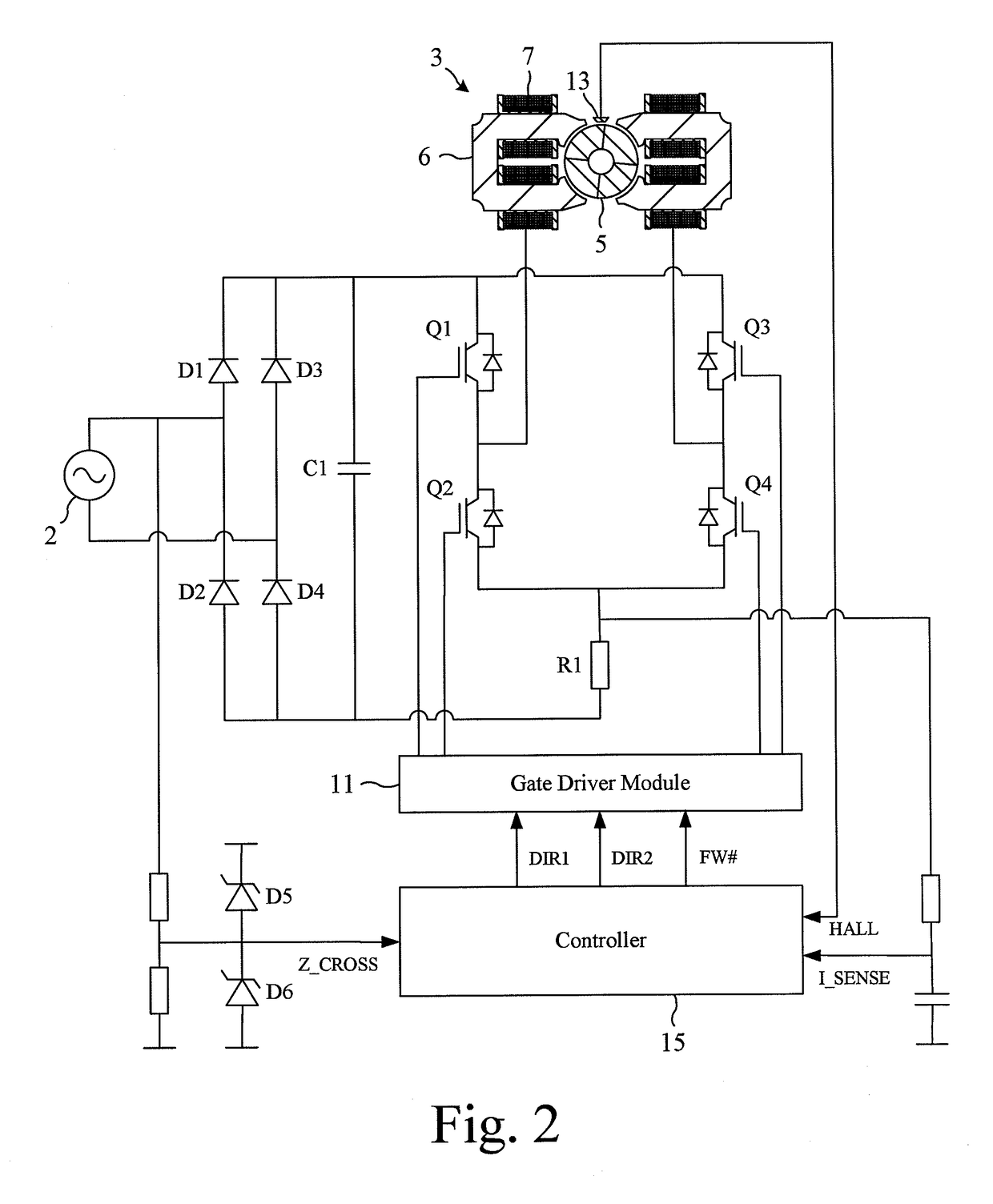
[0025]The motor system 1 of FIGS. 1 and 2 is powered by an AC power supply 2 and comprises a brushless motor 3 and a control system 4.

[0026]The motor 3 comprises a permanent-magnet rotor 5 that rotates relative to a stator 6 having a single phase winding 7.

[0027]The control system 4 comprises a rectifier 8, a DC link filter 9, an inverter 10, a gate driver module 11, a current sensor 12, a rotor-position sensor 13, a zero-cross detector 14, and a controller 15.

[0028]The rectifier 8 comprises a full-wave bridge of four diodes D1-D4 that rectify the output of the AC power supply 2 to provide a DC voltage.

[0029]The DC link filter 9 comprises a capacitor C1 that smoothes the relatively high-frequency ripple that arises from switching of the inverter 10. If required, the DC link filter 9 may additionally smooth the rectified DC voltage at the fundamental frequency.

[0030]The inverter 10 comprises a full bridge of four power switches Q1-Q4 that couple the DC link voltage to the phase windi...


PUM


Abstract

A method of controlling a brushless motor that includes storing a lookup table of control values, periodically obtaining a speed-adjusted control value, and exciting a phase winding of the motor. The speed-adjusted control value is then used to define the phase and / or length of excitation. Obtaining the speed-adjusted control value includes measuring the speed of the motor, increasing or decreasing a speed-adjust variable in the event that the measured speed is greater or less than a threshold, selecting a control value from the lookup table using the measured speed, and adjusting the selected control value using the speed-adjust variable to obtain the speed-adjusted control value. Additionally, a control system that implements the method, and a motor assembly that incorporates the brushless motor and the control system.

Description

REFERENCE TO RELATED APPLICATIONS[0001]This application claims the priority of United Kingdom Application No. 1120191.0, filed Nov. 23, 2011, the entire contents of which are incorporated herein by reference.FIELD OF THE INVENTION[0002]The present invention relates to a method of controlling a brushless motor.BACKGROUND OF THE INVENTION[0003]A brushless motor typically comprises a controller that controls the excitation of phase windings. The controller may adjust the phase and / or the length of excitation in response to changes in the speed of the motor. To this end, the controller may store a lookup table that comprises different control values for different motor speeds. The control values are then used to define the phase and / or the length of excitation.[0004]The control values stored by the lookup table may be those for a nominal motor. Moreover, the control values may be selected such that the speed of the nominal motor, when operating under a nominal load, does not exceed an u...

Claims


Application Information

Patent Timeline
Patent Type & Authority Patents(United States)
IPC IPC(8): H02P23/12H02P6/14H02P6/26H02P29/032H02K19/12H02P6/15
CPCH02P6/26H02P6/153H02P29/032H02P6/15
Inventor DAI, HANPINGCHEN, YULEAVER, MARK EDWARDHINCHLIFFE, SAMUEL WESLEY
Owner DYSON TECH LTD
Why Eureka
Try Eureka