
User interface for camera effects

a user interface and camera technology, applied in the field of computer user interfaces of electronic devices, can solve the problems of cumbersome and inefficient management techniques of camera effects using electronic devices, inability to accurately display visual effects in viewfinders such as captured images and recorded videos, and existing techniques that use complex and time-consuming user interfaces. achieve the effect of improving efficiency, improving efficiency, and improving user satisfaction

Active Publication Date: 2017-07-25
APPLE INC
View PDF30 Cites 124 Cited by
  • Summary
  • Abstract
  • Description
  • Claims
  • Application Information

AI Technical Summary

Benefits of technology

The patent text describes the technical effect of a new patent technique that provides faster and more efficient ways for electronic devices to manage camera effects. These methods and interfaces can replace or complement existing methods and reduce the cognitive burden on users, making it a more efficient and user-friendly interface. The techniques also conserve battery power and increase the time between battery charges, and can provide simulated optical effects and enhanced zooming capabilities without additional hardware components. Overall, these techniques enhance the performance and user satisfaction of electronic devices and improve their overall effectiveness and efficiency.

Problems solved by technology

Some techniques for managing camera effects using electronic devices, however, are generally cumbersome and inefficient.
For example, modifying the visual effects in viewfinders such that captured images and recorded videos exhibit the visual effects often requires extensive user input and is imprecise.
For example, some existing techniques use a complex and time-consuming user interface, which may include multiple key presses or keystrokes.
Existing techniques require more time than necessary, wasting user time and device energy.

Method used


Image

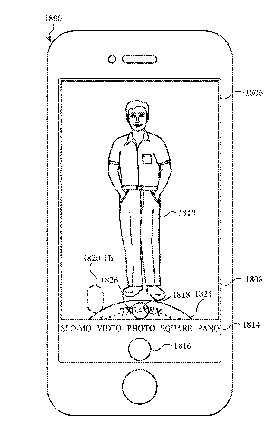
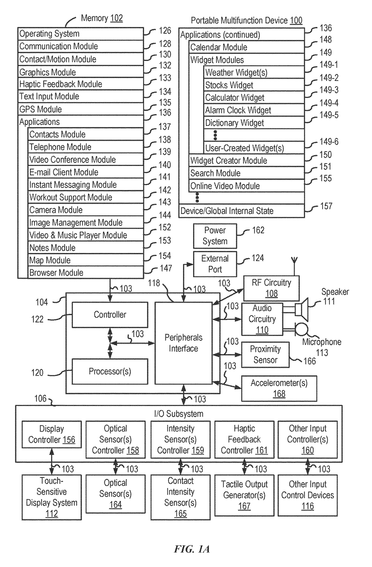
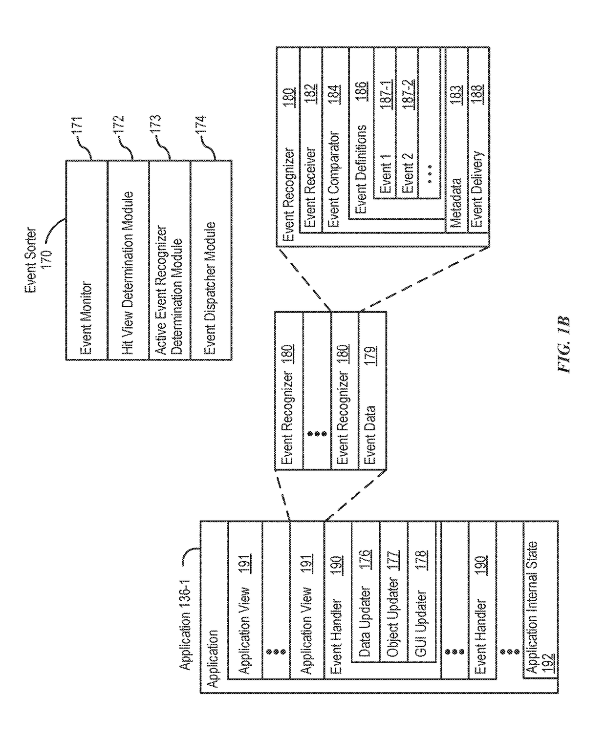
  • User interface for camera effects
  • User interface for camera effects
  • User interface for camera effects

Examples


Embodiment Construction

[0069]The following description sets forth exemplary methods, parameters, and the like. It should be recognized, however, that such description is not intended as a limitation on the scope of the present disclosure but is instead provided as a description of exemplary embodiments.

[0070]Efficient device packaging allows desirable, highly-portable electronic devices to be designed and manufactured. But, some electronic device components complicate the design of smaller devices, particularly thinner ones. Camera sensors and related components constitute an example: they involve physical components organized along optical trains that lend to thicker designs. Consider, for instance, the ability of a camera (e.g., CCD sensor and related lenses) to perform variable optical zooming depends on the arrangement of moveable (e.g., motorized) lens(es) among an optical train. When incorporated into cellular phones, the usual orientation of camera components is at odds with the form-factor of the ...


PUM


Abstract

The present disclosure generally relates to user interfaces. In some examples, the electronic device transitions between user interfaces for capturing photos based on data received from a first camera and a second camera. In some examples, the electronic device provides enhanced zooming capabilities that result in visual pleasing results for a displayed digital viewfinder and for captured videos. In some examples, the electronic device provides user interfaces for transitioning a digital viewfinder between a first camera with an applied digital zoom to a second camera with no digital zoom. In some examples, the electronic device prepares to capture media at various magnification levels. In some examples, the electronic device enhanced capabilities for navigating through a plurality of values.

Description

CROSS-REFERENCE TO RELATED APPLICATIONS[0001]This application claims priority to the following provisional applications: U.S. Patent Application Ser. No. 62 / 349,059, entitled “USER INTERFACE FOR CAMERA EFFECTS”, filed Jun. 12, 2016; U.S. Patent Application Ser. No. 62 / 384,140, entitled “USER INTERFACE FOR CAMERA EFFECTS”, filed Sep. 6, 2016; and U.S. Patent Application Ser. No. 62 / 397,860, entitled “USER INTERFACE FOR CAMERA EFFECTS”, filed Sep. 21, 2016. The content of these applications is hereby incorporated by reference in their entirety.FIELD[0002]The present disclosure relates generally to computer user interfaces of electronic devices, particularly devices having built-in cameras.BACKGROUND[0003]The use of electronic devices for recording videos and taking pictures has increased significantly in recent years. Exemplary electronic devices for recording videos and taking pictures include smart phones and hand-held cameras. Such devices frequently include a viewfinder, which the...

Claims


Application Information

Patent Timeline
IPC IPC(8): H04N5/232G06F3/048H04N5/262G06F3/0484G06F3/0481G06F3/0488H04N13/239
CPCH04N5/23216H04N5/23296H04N5/2628H04N5/23293H04N5/23212G06F3/04883G06F3/04847G06F3/04817H04N5/262H04N13/239H04N13/271G03B19/22G06F3/0488G06F3/0484G06F2203/04808G03B2205/00G03B2217/002G06F2203/04803G06F3/0482G06T2207/30204G06F2203/04806G06T2207/10028H04N23/45H04N23/959H04N23/67H04N23/64H04N23/611H04N23/62H04N23/65H04N23/667H04N23/632H04N23/69H04N23/63H04N23/90G06T5/70G06F3/04142H04N23/675H04N23/61H04N23/651H04N23/634H04N23/631H04N23/635H04N23/695H04M1/0264H04M2250/52
Inventor MANZARI, BEHKISH J.PIVO{HACEK OVERPRESTON, DANIEL TRENT
Owner APPLE INC
Learn More