Method for driving reflective LCD panel

a technology of liquid crystal display panel and reflective lcd panel, which is applied in the direction of electric digital data processing, instruments, computing, etc., can solve the problems of marble mura deformation and image sticking to the display panel

Active Publication Date: 2017-08-01
HIMAX DISPLAY INC
View PDF16 Cites 0 Cited by
  • Summary
  • Abstract
  • Description
  • Claims
  • Application Information

AI Technical Summary

Benefits of technology

[0008]Accordingly, the invention is directed to a method for driving a reflective LCD panel, which can avoid the display panel from producing the defects of marble mura and image sticking.

Problems solved by technology

The asymmetric lighted up time would lead to defects of marble mura and image sticking present on the display panel.

Method used


Image

  • Method for driving reflective LCD panel
  • Method for driving reflective LCD panel
  • Method for driving reflective LCD panel

Examples


Embodiment Construction

[0022]Reference will now be made in detail to the preferred embodiments of the invention, examples of which are illustrated in the accompanying drawings. Wherever possible, the same reference numbers are used in the drawings and the description to refer to the same or like parts.

[0023]In following exemplary embodiments, an LCoS panel is selected, but not limited to, for serving as the implemented sample of the reflective LCD panel. In general speaking, in the LCoS panel, the photo-induced current leakage is almost unavoidable. The current leakage easily leads the liquid crystal molecules subject to a DC bias, which further causes the displaying area of the LCD panel producing serious defects of marble mura and image sticking.

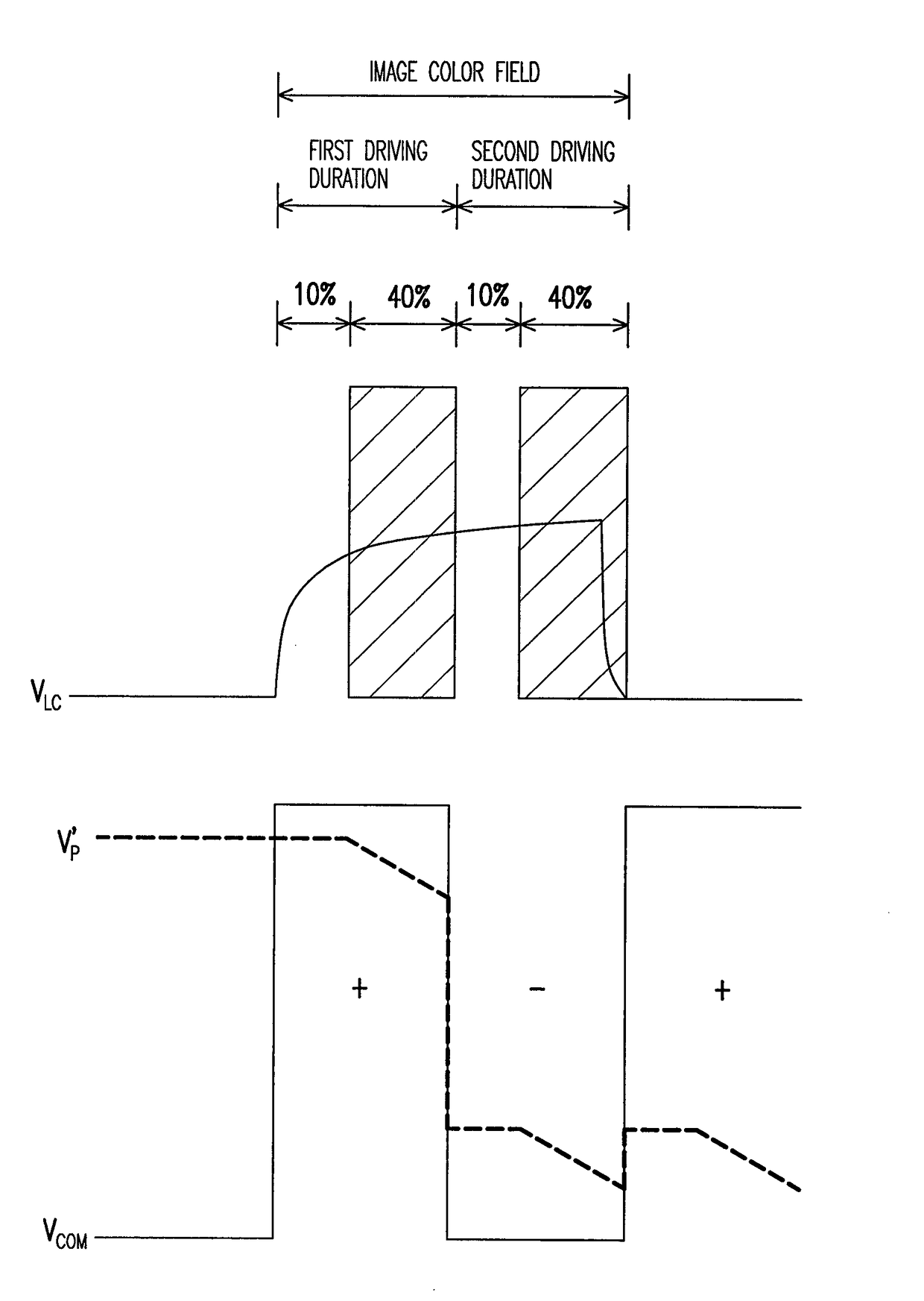
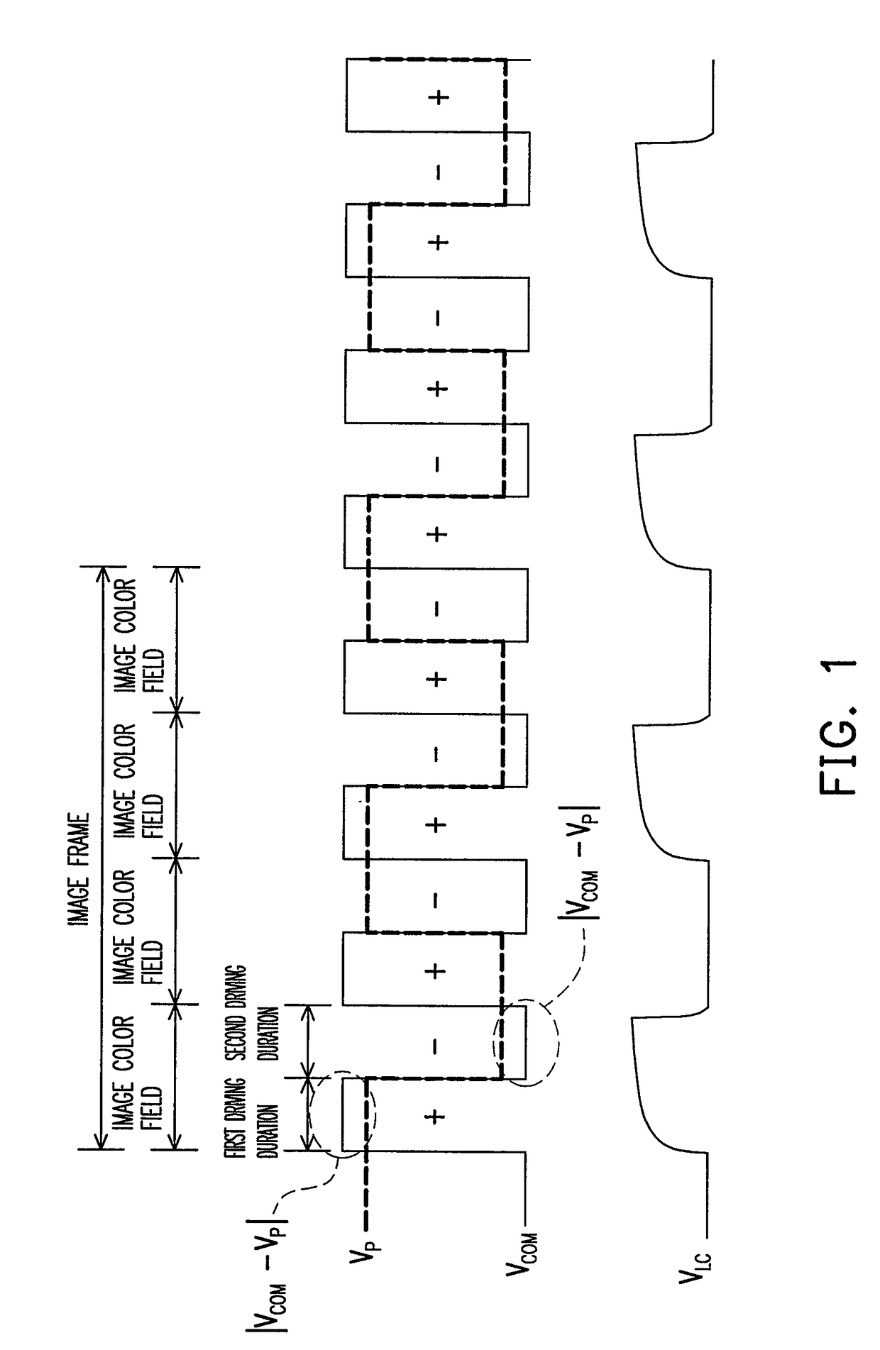
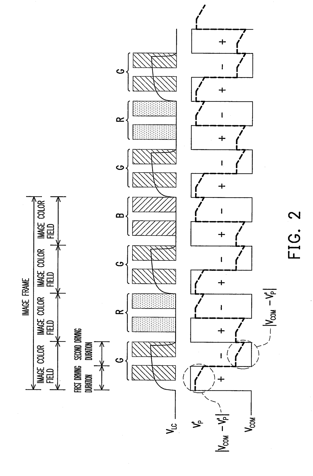
[0024]In an exemplary embodiment of the invention, a method for driving an LCoS panel is provided. The above-mentioned driving method provides lighted up periods with the same length in the driving durations with different polarities during a same image color fi...


PUM


Abstract

A method for driving a reflective LCD panel is provided. The driving method includes following steps: the reflective LCD panel is driven by a driving signal with alternate positive and negative polarities, wherein the driving signal has positive polarity for a first driving duration and the driving signal has negative polarity for a second driving duration; a color beam is provided to irradiate the reflective LCD panel during a partial time period of the first driving duration; and the color beam is provided to irradiate the reflective LCD panel during a partial time period of the second driving duration.

Description

CROSS-REFERENCE TO RELATED APPLICATION[0001]This application claims the priority benefit of U.S. provisional application Ser. No. 61 / 367,850, filed on Jul. 26, 2010. The entirety of the above-mentioned patent application is hereby incorporated by reference herein and made a part of this specification.BACKGROUND OF THE INVENTION[0002]1. Field of the Invention[0003]The invention generally relates to a method for driving a liquid crystal display panel (LCD panel), and more particularly, to a method for driving a reflective LCD panel.[0004]2. Description of Related Art[0005]In a color display, each color spot comprises in fact three color beams with different colors. Generally, the color spot is formed by mixing up a red beam, a green beam and a blue beam. When lights with different colors enter human eyes, the lights are mixed up on the retinas thereof so as to have a colorful perception, wherein the above-mentioned mechanism of producing colourful perceptions is referred as color sequ...

Claims


Application Information

Patent Timeline
Patent Type & Authority Patents(United States)
IPC IPC(8): G09G3/36G09G3/34
CPCG09G3/3614G09G3/3413G09G3/3655G09G2310/0235G09G2310/08G09G2320/0242
Inventor LI, YUET-WINGWU, CHIEN-LIANGFAN-CHIANG, KUAN-HSU
Owner HIMAX DISPLAY INC
Why Eureka
Try Eureka