Cleaning device, process cartridge and image forming apparatus

a cleaning device and cartridge technology, applied in the field of cleaning devices, can solve the problems of difficult removal of residual toner by the cleaning blade, increased cost, space requirements, etc., and achieve the effect of satisfactorily removing residual toner and maintaining good image forming over long periods of tim

Active Publication Date: 2020-06-25
CANON KK
View PDF0 Cites 0 Cited by
  • Summary
  • Abstract
  • Description
  • Claims
  • Application Information

AI Technical Summary

Benefits of technology

[0049]The present invention allows removing satisfactorily residual toner by means of a cleaning blade, and maintaining good image forming over long

Problems solved by technology

H06-130870 the charging device is used in the image forming apparatus; accordingly, the costs involved are greater, and space is required for the charging device, a high-voltage output device and so forth, which entails a larger size of the image forming apparatus.
In turn, this makes removal of th

Method used


Image

  • Cleaning device, process cartridge and image forming apparatus
  • Cleaning device, process cartridge and image forming apparatus
  • Cleaning device, process cartridge and image forming apparatus

Examples


embodiment 1

[0083]Embodiment 1 will be explained next. The following materials are used as the recovery sheet member 14 of Embodiment 1.

[0084]Material (Base Material): polyphenylene sulfide (PPS) sheet

[0085]Thickness: 38 μm

[0086]Work function: 5.80 eV

[0087]Young's modulus: 3000 N / m2

[0088]Poisson's ratio: 0.38

[0089]The contact conditions of the recovery sheet member 14 with the photosensitive drum 1 are given below. The recovery sheet member 14 is joined to the frame 15 by laser welding.

[0090]Penetration amount: 3.4 (μm)

[0091]Setting angle: 28.6 (°)

[0092]Deflection amount δ: 1.24 (mm)

[0093]Contact pressure: 8.72×10⁻⁴ (N / mm)

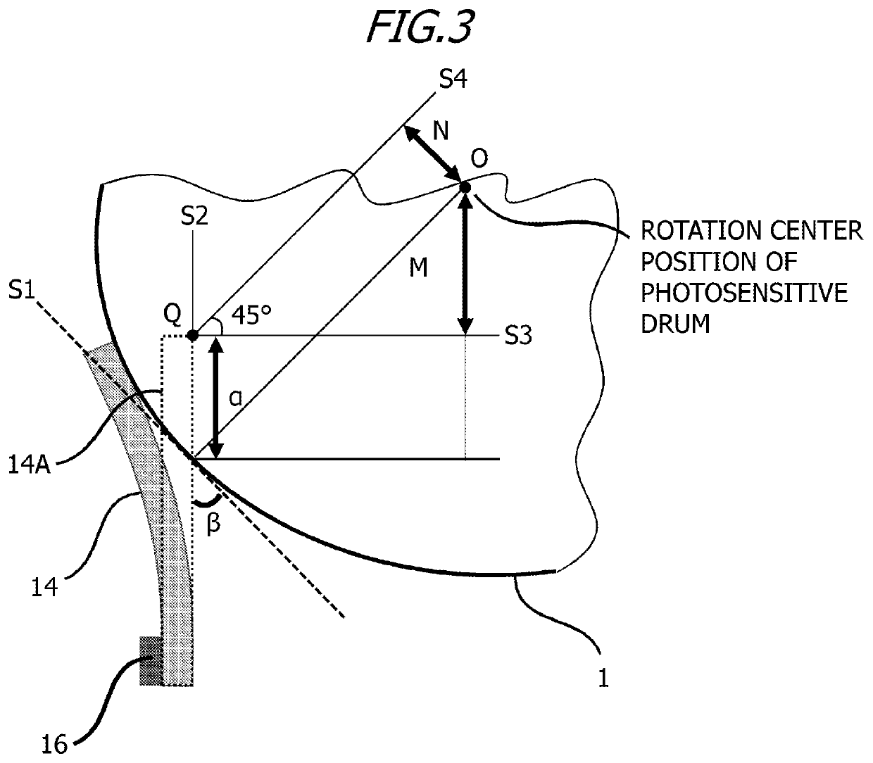
[0094]The penetration amount and the setting angle will be explained next with reference to FIG. 3.

[0095]The reference symbol α illustrated in FIG. 3 is defined as the penetration amount (mm) and the reference symbol β is defined as the setting angle (°). The penetration amount α denotes the degree by which the recovery sheet member 14 would penetrate into the outline of the ...

embodiment 2

[0144]Embodiment 2 differs from Embodiment 1 in that herein the material of the recovery sheet member 14 is modified.

[0145]Recovery Sheet Member 14

[0146]Material (Base Material): polytetrafluoroethylene (PTFE) sheet (Teflon (registered trademark))

[0147]Thickness: 50 (μm)

[0148]Work function: 6.0 (eV)

[0149]Flexural elasticity modulus: 560 (N / m2)

[0150]Poisson's ratio: 0.46

[0151]The contact conditions of the recovery sheet member 14 with the photosensitive drum 1 are given below. The recovery sheet member 14 is joined to the frame 15 by laser welding.

[0152]Penetration amount: 3.4 (μm)

[0153]Setting angle: 28.6(°)

[0154]Deflection amount δ: 1.24 (mm)

[0155]Contact pressure: 4.02×10⁻⁴ (N / mm)

embodiment 3

[0156]Embodiment 3 differs from Embodiment 1 in that the method for joining the recovery sheet member 14 to the frame 15 is modified.

[0157]In Embodiment 3, a double-sided tape is affixed to the frame 15, and the recovery sheet member 14 is provided on the double-sided tape, to thereby fix the recovery sheet member 14 to the frame 15. The contact conditions of the recovery sheet member 14 with the photosensitive drum 1 are given below.

[0158]Penetration amount: 4.9 (μm)

[0159]Setting angle: 37.3(°)

[0160]Deflection amount δ: 2.24 (mm)

[0161]Contact pressure: 1.57×10⁻³ (N / mm)


PUM


Abstract

A cleaning device, including: a cleaning frame; a cleaning member having one end and the other end, the image bearing member being capable of rotating and bearing a developer image formed of a developer so as to remove the developer remaining on the image bearing member after transfer of the developer image from the image bearing member; and a sheet member having flexibility and having one end and the other end; wherein a work function W (D) of the developer and a work function W (S) of the sheet member satisfy 0≤W(D)−W(S)≤0.23 and the developer includes inorganic particles, and at least one kind of the inorganic particles has an average primary particle diameter of 50 nm or larger.

Description

BACKGROUND OF THE INVENTIONField of the Invention[0001]The present invention relates to a cleaning device for removing a developer that remains of an electrophotographic photosensitive member after transfer of a developer image to a recording medium from the photosensitive member.Description of the Related Art[0002]Electrostatic recording systems, electrophotographic recording systems and the like are often used conventionally in image forming apparatuses such as copiers and printers. In these image forming apparatuses, an electrostatic latent image is formed on a photosensitive member, and then image forming is performed through transfer of a developer image to a recording material. In such image forming apparatuses, there remains developer that has failed to be transferred to the photosensitive member drum after transfer, and hence the developer is ordinarily removed by a cleaning device that utilizes for instance an elastic blade. Recent years have witnessed a trend towards the u...

Claims


Application Information

Patent Timeline
IPC IPC(8): G03G21/18G03G21/16G03G21/10
CPCG03G21/10G03G21/0029G03G21/1814G03G21/169G03G2221/1648G03G21/1832G03G21/0017G03G21/105G03G21/12G03G21/0005G03G2221/0047G03G2221/1627
Inventor TOKIWA, SHUHEIKANAZAWA, TAKAYUKI
Owner CANON KK
Why Eureka
Try Eureka