
Photosensitive device, image forming apparatus and method for forming images

a technology of image forming apparatus and photosensitive device, which is applied in the direction of instrumentation, manifolding, electrographic process, etc., can solve the problems of extreme rise of running cost, shorten the life of the photosensitive member, and drawback of image forming, etc., to achieve excellent image forming, reduce the cost of photosensitive member, and reduce the effect of rising cos

Inactive Publication Date: 2005-07-26
KK TOSHIBA
View PDF5 Cites 2 Cited by
  • Summary
  • Abstract
  • Description
  • Claims
  • Application Information

AI Technical Summary

Benefits of technology

[0014]In accordance with the construction mentioned above, the present invention is intended to realize an image-forming apparatus that can suppress rising of the cost thereof and provide a high quality image. That is, slipperiness of the photosensitive sheet is not deteriorated during winding operation because of a regulating member to regulate the contact force between the cylinder and the photosensitive sheet. Thus, misalignment of the photosensitive sheet with the drum or stretch thereof caused by the transferring operation may be suppressed while image-forming operation is executed so as to carry out excellent image-forming.

Problems solved by technology

Consequently, an excess load is imposed on the photosensitive member while the transferred images are obtained by the pressure transfer method, so that it is feared that life of the photosensitive member may be shortened.
Furthermore, frequent replaces of the photosensitive members may result in an extreme rise of running cost, because generally a large and expensive photosensitive drum is used in the case of the liquid-process type image-forming apparatus for obtaining full color images.
Therefore, the photosensitive sheet may be off the drum or become stretched resulting in a drawback about image forming.

Method used


Image

  • Photosensitive device, image forming apparatus and method for forming images
  • Photosensitive device, image forming apparatus and method for forming images
  • Photosensitive device, image forming apparatus and method for forming images

Examples


Embodiment Construction

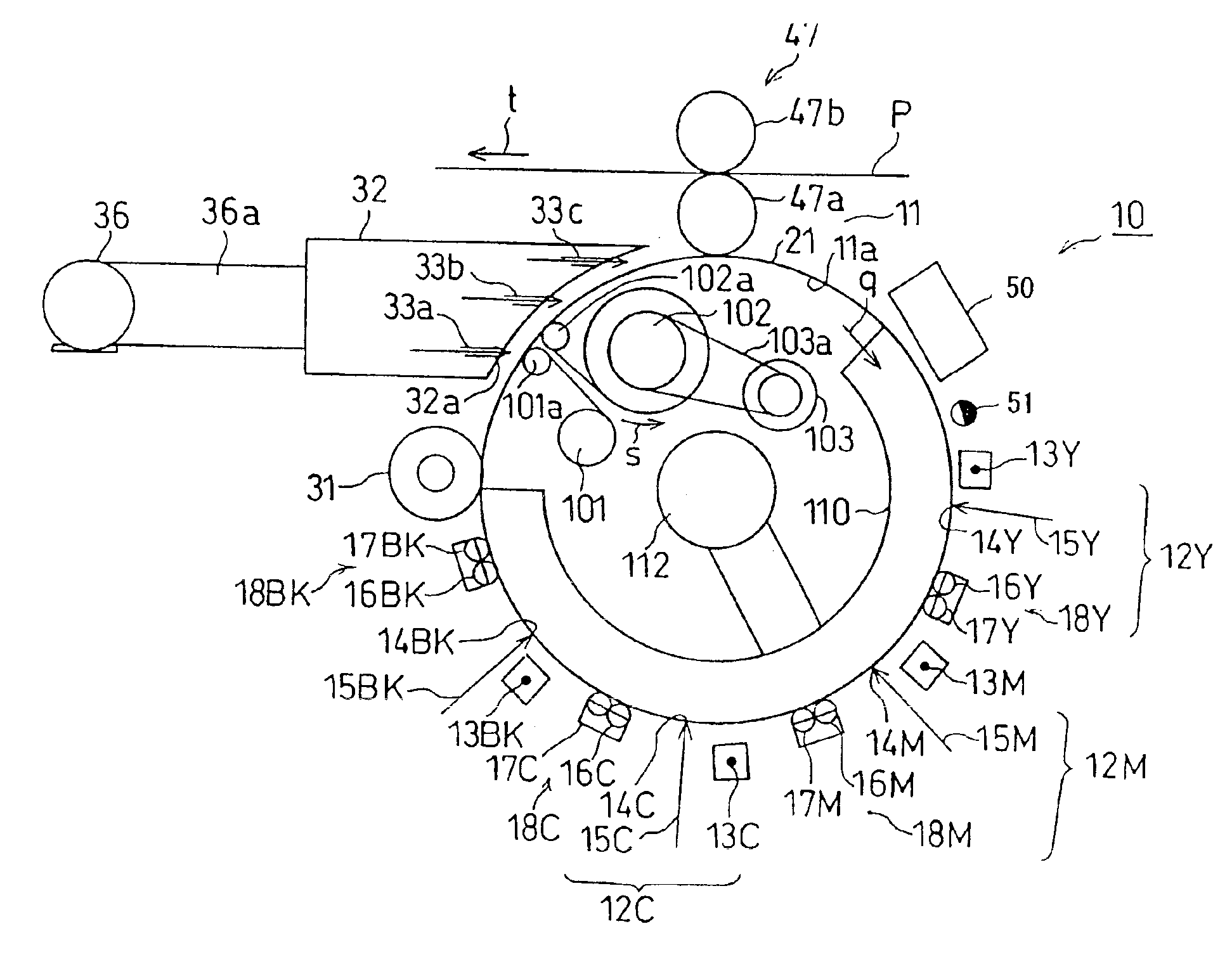
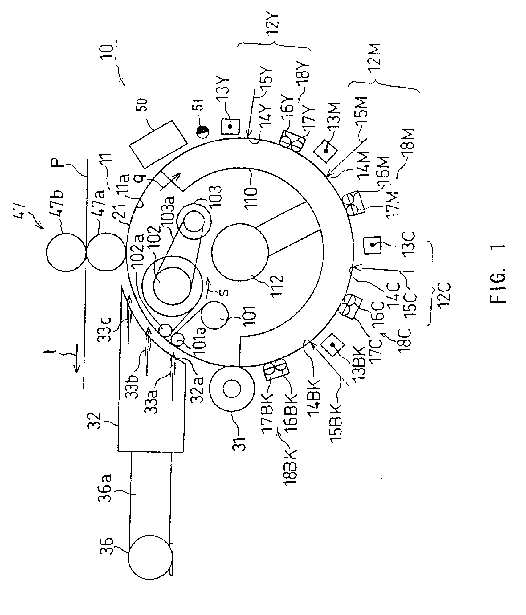
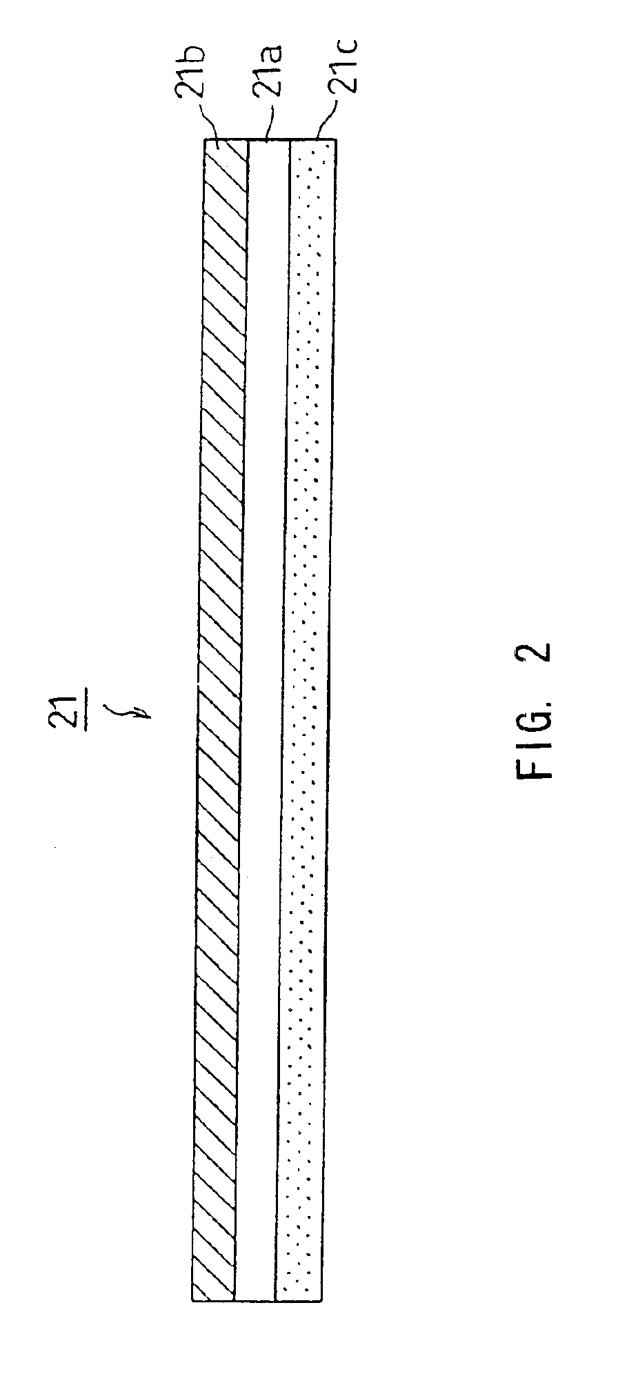
[0020]Now, some embodiments of the present invention are described in detail referring to FIGS. 1 to 4. FIG. 1 shows an image-forming portion 10 of liquid-process type full color electro-photographic apparatus that is the image-forming apparatus of the invention. The image-forming portion 10 includes a drum 11a, which is a cylinder, wrapped with a long and flexible photosensitive sheet 21 having a photosensitive layer, and a photosensitive device 11. A developed image is formed on the photosensitive layer.

[0021]On the periphery of the photosensitive device 11, first to fourth image-forming units 12Y, 12M, 12C and 12BK are positioned on the photosensitive sheet 21 sequentially along the rotation direction of the drum 11a shown as an arrow q in FIG. 1. The image-forming units 12Y, 12M, 12C and 12BK are image-forming members forming developed images by the aid of liquid carriers such as solvents of yellow (Y), magenta (M), cyan (C) and black (BK), respectively, and of respective liquid...


PUM


Abstract

A photosensitive device has a cylinder, a photosensitive sheet slidably wrapping outer surface of the cylinder, and a feeding roller in the cylinder. The feeding roller feeds the photosensitive sheet to the outer surface of the cylinder sequentially. The photosensitive device also has a winding roller in the cylinder. The winding roller rolls the photosensitive sheet sequentially from the outer surface of the cylinder. The photosensitive device also has an adjusting member for adjusting contact force emerged between the cylinder and the photosensitive sheet.

Description

BACKGROUND OF THE INVENTION[0001]This invention relates to a photosensitive device, an image forming apparatus and a method for forming images using them, and more specifically, to those devices and method using a long photosensitive sheet to be rolled up after usage.[0002]A pressure transfer method is known as a prior-art transferring method for transferring the toner image formed on a photosensitive member to a medium, in order to obtain stable transferred images regardless of the sort of the medium, or of change of the environment. In the pressure transfer method, toner particles on the surface of the photosensitive member is transferred to the medium by the aid of adherence of the toner particles by pressing the photosensitive member to the medium.[0003]For example, in a liquid-process type image-forming apparatus using liquid developer, which can realize full color images having a quality comparable to that of offset printing, the pressure transfer method is adopted. That is be...

Claims


Application Information

Patent Timeline
Patent Type & Authority Patents(United States)
IPC IPC(8): B41J2/00B41L3/00B41L3/02B41M1/14G03G5/10G03G21/00G03G15/16G03G15/00
CPCG03G15/751G03G2215/00966
Inventor NUKADA, HIDEKITAKAHARA, KENICHI
Owner KK TOSHIBA
Learn More