
Circular base station antenna array and method of reconfiguring a radiation pattern

a radiation pattern and antenna array technology, applied in the field of wireless communication, can solve the problems of limiting throughput, cost and time-consuming changes, and differentiating between antenna combinations,

Active Publication Date: 2017-08-01
COMMSCOPE TECH LLC
View PDF29 Cites 8 Cited by
  • Summary
  • Abstract
  • Description
  • Claims
  • Application Information

AI Technical Summary

Problems solved by technology

However, such a pattern may limit throughput if the number of users in a given area is increased.
However, such a change in shape and / or radiation pattern typically requires replacing the installed base station antenna and / or changing its orientation.
Such changes are costly and time consuming.

Method used


Image

  • Circular base station antenna array and method of reconfiguring a radiation pattern
  • Circular base station antenna array and method of reconfiguring a radiation pattern
  • Circular base station antenna array and method of reconfiguring a radiation pattern

Examples


Embodiment Construction

[0021]Certain terminology is used in the following description for convenience only and is not limiting. The words “lower,”“bottom,”“upper” and “top” designate directions in the drawings to which reference is made. Unless specifically set forth herein, the terms “a,”“an” and “the” are not limited to one element, but instead should be read as meaning “at least one.”

[0022]The terminology includes the words noted above, derivatives thereof and words of similar import. It should also be understood that the terms “about,”“approximately,”“generally,”“substantially” and like terms, used herein when referring to a dimension or characteristic of a component of the invention, indicate that the described dimension / characteristic is not a strict boundary or parameter and does not exclude minor variations therefrom that are functionally similar. At a minimum, such references that include a numerical parameter would include variations that, using mathematical and industrial principles accepted in...


PUM


Abstract

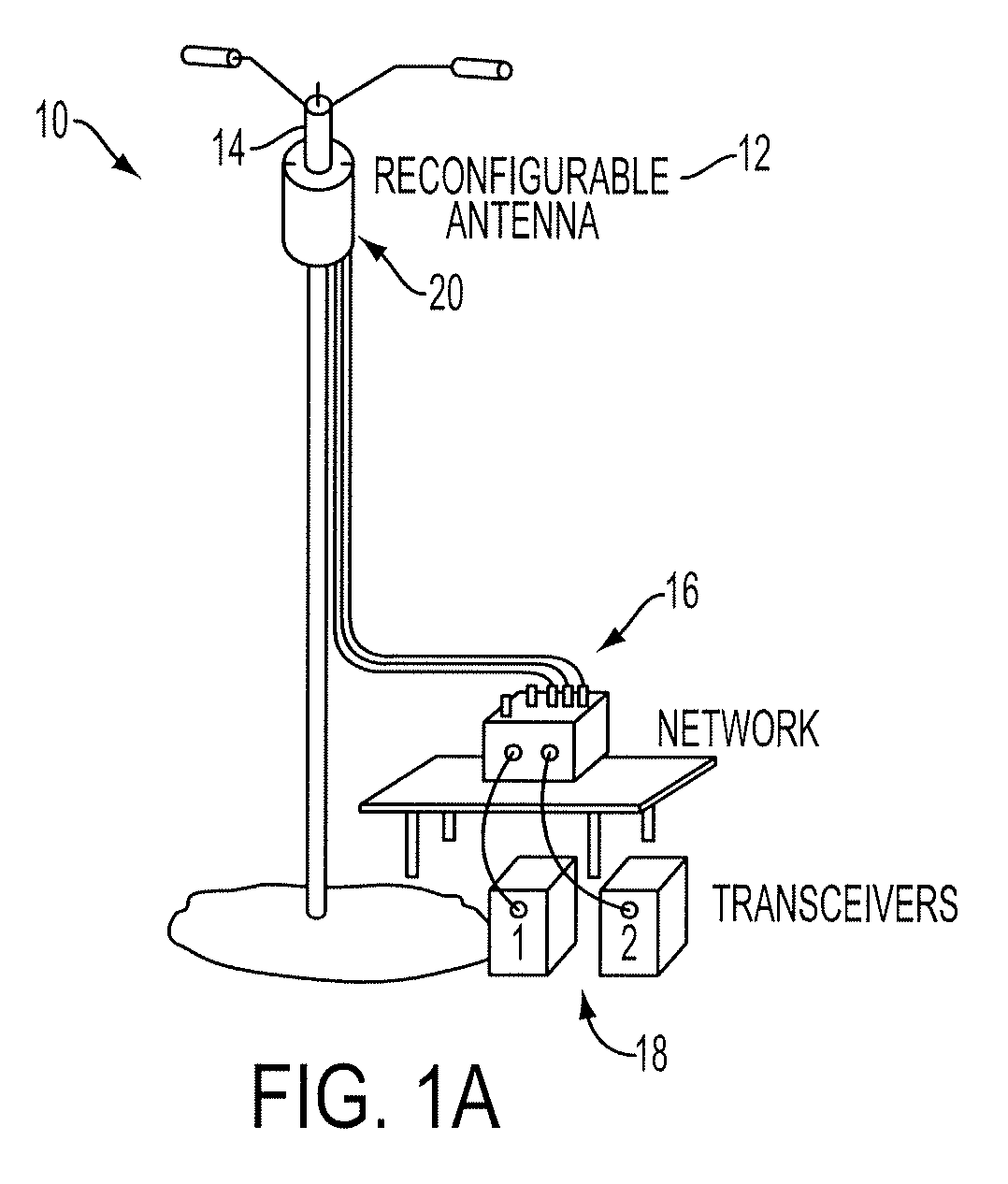
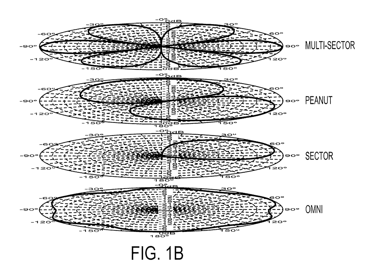
Aspects of the present disclosure may be directed to a reconfigurable antenna system including a reconfigurable antenna capable of providing various types of radiation patterns without having to be replaced or needing its orientation changed. The reconfigurable antenna may create various types of quasi-omni directional radiation patterns of different shapes depending on the environment.

Description

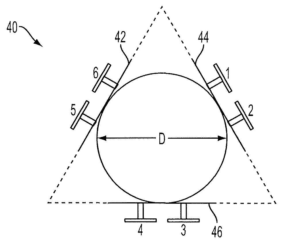
BACKGROUND OF THE INVENTION[0001]Various aspects of the present disclosure may relate to wireless communications, and, more particularly, to base station antennae radiation pattern control.[0002]To provide increased coverage and throughput, additional base stations (e.g., small-cell base stations) are being deployed along with macro-cell base stations, especially in urban areas. An antenna system of a small-cell base station may be placed around a support structure, such as a pole and may operate as a circular array. Accordingly, the circular array may operate as an array of antenna elements with phase centers located on a circle, and may be used to form a quasi-omnidirectional radiation pattern in the azimuth plane.[0003]Even though a quasi-omnidirectional radiation pattern may be desirable for many scenarios and environments, other types of radiation patterns, and even other shapes of quasi-omnidirectional radiation patterns may be advantageous. For example, a quasi-omnidirectiona...

Claims


Application Information

Patent Timeline
Patent Type & Authority Patents(United States)
IPC IPC(8): H01Q21/08H01Q1/24H01Q3/26H01Q21/29H01Q21/20H01Q1/44
CPCH01Q21/29H01Q1/246H01Q3/26H01Q21/20H01Q21/205H01Q1/44H01Q3/24H01Q3/28H01Q3/34H04B7/04H04W16/28H01Q3/242H01Q21/293
Inventor CHISTYAKOV, NIKOLAYMICHAELIS, SCOTT LYNNBALTER, ZOYA
Owner COMMSCOPE TECH LLC
Learn More