Environmentally sensitive reconfigurable antenna

a reconfigurable antenna and environment-friendly technology, applied in the field of antenna systems, can solve the problems of affecting the operation of the resonant antenna, the resonant antenna is easily blocked by typical obstructions, and the transmission of data is expensive, so as to achieve the effect of modifying the resonance and electromagnetic radiation properties

Active Publication Date: 2006-11-02
RGT UNIV OF CALIFORNIA
View PDF4 Cites 30 Cited by
  • Summary
  • Abstract
  • Description
  • Claims
  • Application Information

AI Technical Summary

Benefits of technology

[0005] The present invention provides an improved antenna whose resonance and electromagnetic radiation properties can be modified by environmental and acoustic conditions. The reconfiguring antenna acts to provide a way to transmit wireless information about the local environment without the need for local power.
[0008] The changing configuration of the antenna can be used to passively and wirelessly couple the local environmental condition or local acoustic wave to a receiver. By sending electromagnetic radiation of known frequencies to the sensing antenna, one can monitor the absorbed or reflected radiation at one or more frequencies. The efficiency of absorption or reflection by the antenna will be modulated by the local environment or acoustic energy, thus affecting the monitored absorbed or reflected radiation. In this way, the environmental and acoustic information can be passively and wirelessly transmitted to an external source.
[0010] The sensor system advantageously requires no power, but can be interrogated remotely by wireless means. The simplicity of the device and passive operation means the device can be deployed over large regions while still enabling remote readout. Furthermore, since the interrogating system can use directional antennas, the interrogating radiation can be highly localized, e.g., through the use of a “pencil beam”. Thus the location of the sensors can be determined by the interrogating system, allowing true geographic mapping of the sensor networks.

Problems solved by technology

Light based systems are readily blocked by typical obstructions such as buildings, trees, and vegetation.
This method is bulky, expensive, and can only transmit data at short distances.
The need for a powered sensor / transmitter severely limits the deployment of such sensors in large scale such as over large geographic regions or as part of the civil infrastructure.
The efficiency of absorption or reflection by the antenna will be modulated by the local environment or acoustic energy, thus affecting the monitored absorbed or reflected radiation.

Method used


Image

  • Environmentally sensitive reconfigurable antenna
  • Environmentally sensitive reconfigurable antenna
  • Environmentally sensitive reconfigurable antenna

Examples


second embodiment

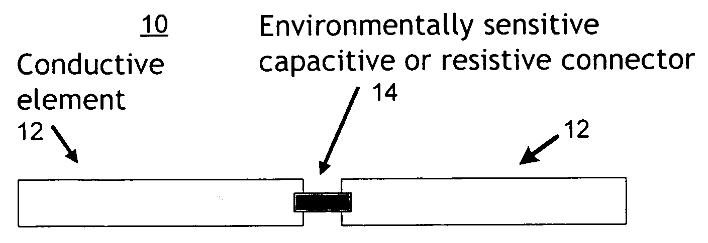
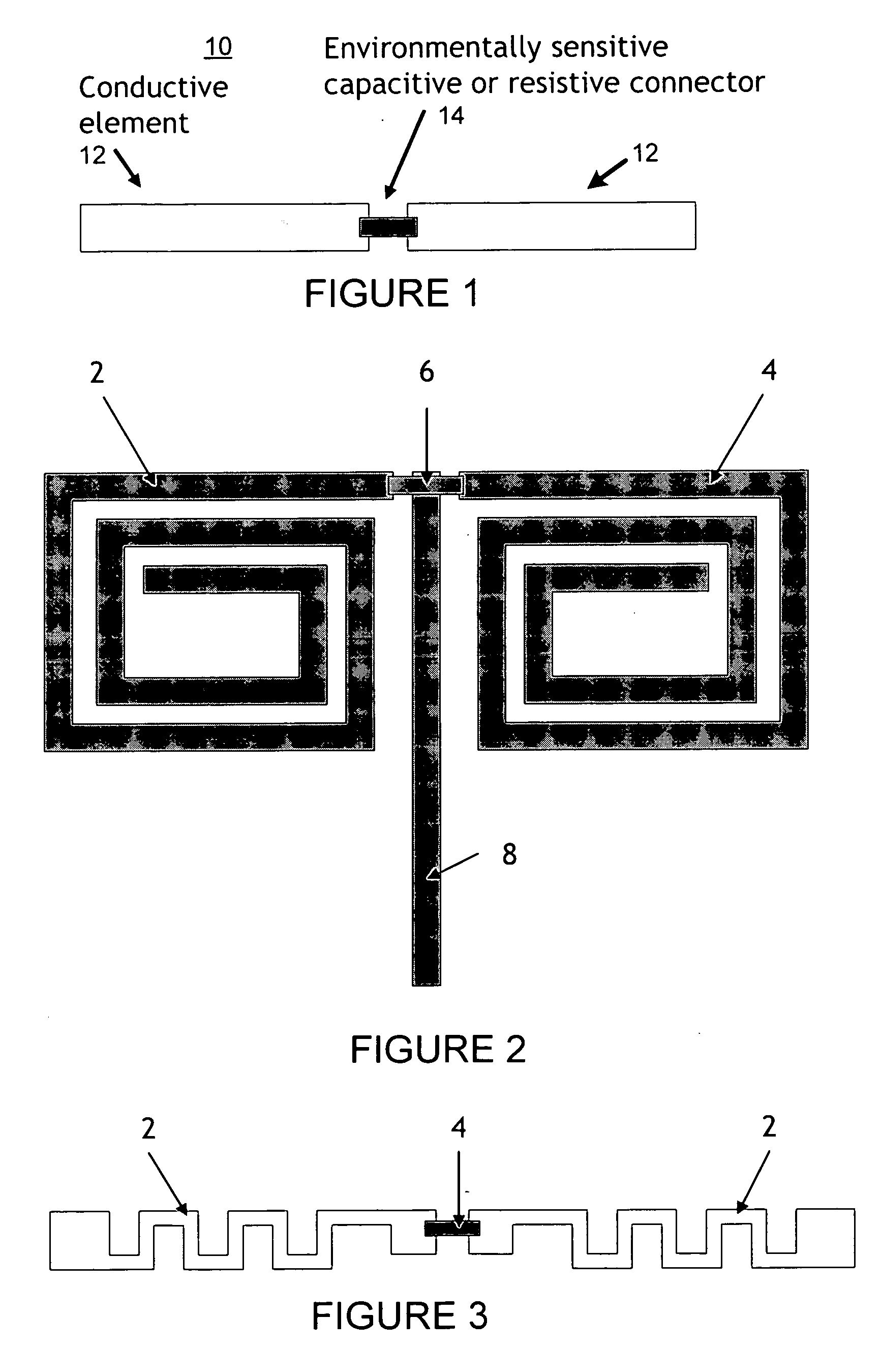
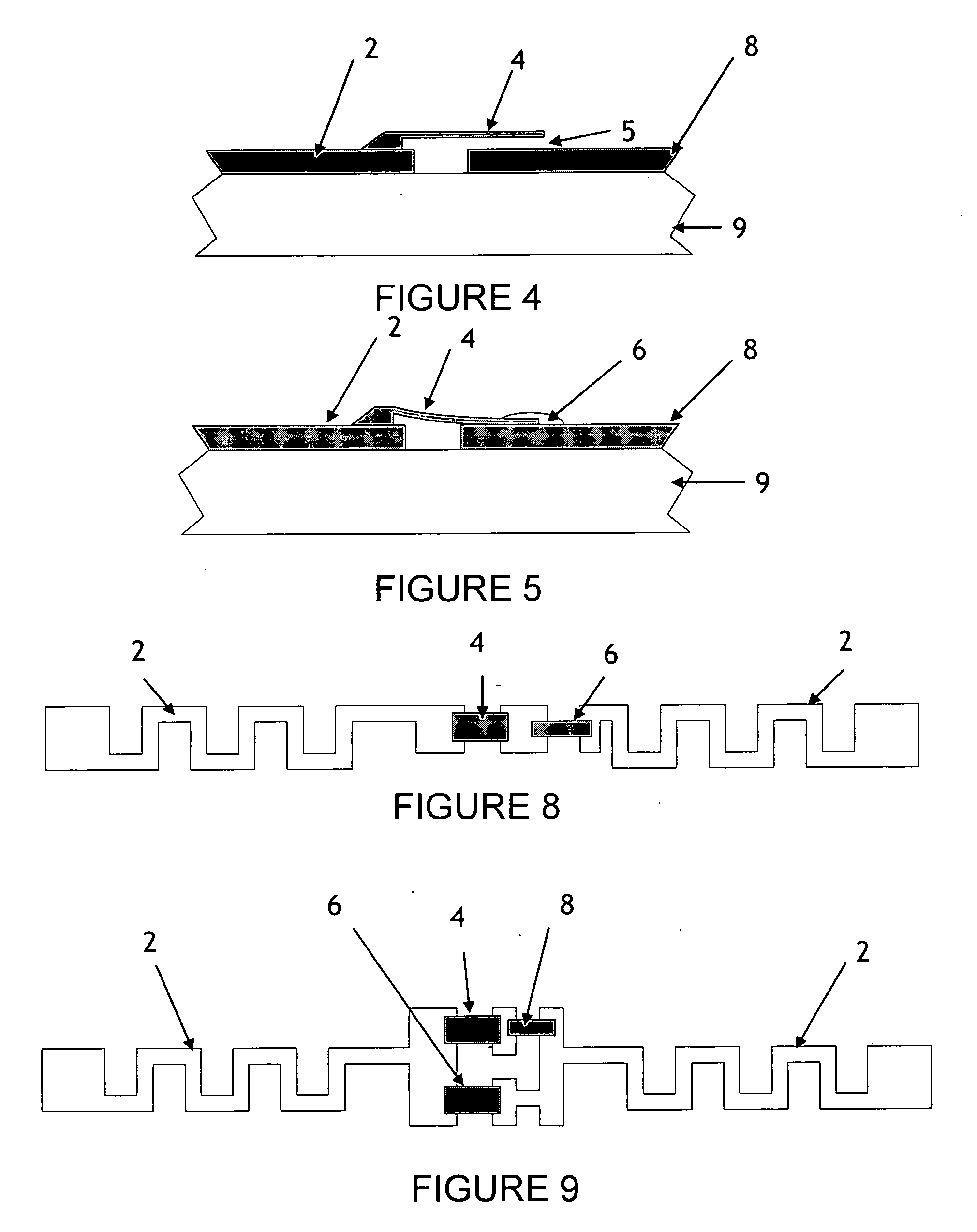
[0036] In the chemically sensitive reconfigurable antenna 210, the connector (14, FIG. 1) is made from a first conductive material in close proximity to a second conductor, forming a capacitor. The first conductive material is coated by a chemically reactive surface designed to adsorb specific biological or chemical species. When the new species are adsorbed, the first conductor experiences a stress and changes its position with respect to the second conductor, thereby changing the capacitance of the antenna connector, and changing the radiation properties of the antenna. In some cases, the moving conductor can form a complete electrical connection, so that the coupling becomes a completed circuit.

third embodiment

[0037] In the chemically sensitive reconfigurable antenna 210, the sensing element can be made with a material that corrodes in the presence of the chemical of biological species of interest. The material can be conductive or dielectric, and it can form a capacitive or resistive bridge between two or more conductors in the antenna. The presence of certain chemical or biological species causes the material to corrode, thereby changing the capacitance or resistance of the connector. In some cases the corroded material can allow a spring loaded element to short or open between two conductors.

[0038] The use of multiple capacitive elements with different chemical affinities can be used to monitor multiple chemical species. The connectors can be placed strategically at different points on the antenna. In this way, a single antenna can be used to monitor multiple chemical and biological species at once. Furthermore, the signal for different chemical and biological detections shows up as di...


PUM


Abstract

An antenna whose resonance and electromagnetic radiation properties can be modified by environmental conditions, acoustic conditions, and the like. The reconfiguring antenna acts to facilitate wireless transmission of information about the local environment without the need for local power.

Description

CROSS-REFERENCE TO RELATED APPLICATIONS [0001] This application claims the benefit of U.S. Provisional Application No. 60 / 662,161 filed Mar. 15, 2005, which application is incorporated herein by reference.FIELD OF THE INVENTION [0002] The present invention relates to antenna systems and, more particularly, to an antenna system that changes the nature of its transmission and reception of electromagnetic radiation based on local environmental conditions. BACKGROUND OF THE INVENTION [0003] With the exception of light-based sensors that change their light interaction properties, all sensors require some power in order to operate and provide a signal to a remote source. Light based systems are readily blocked by typical obstructions such as buildings, trees, and vegetation. Some wireless systems require the use of on-board circuitry that temporarily charges up a battery or capacitor in the presence of an externally applied RF radiation, then use this electrical energy to re-transmit sign...

Claims


Application Information

Patent Timeline
Patent Type & Authority Applications(United States)
IPC IPC(8): G08B13/14
CPCG08B13/2417H01Q9/065H01Q9/285H01Q9/28H01Q9/16
Inventor LI, GUANN-PYNGBACHMAN, MARK
Owner RGT UNIV OF CALIFORNIA
Why Eureka
Try Eureka