Defrost apparatus and method thereof

a technology of defrosting apparatus and defrosting method, which is applied in the direction of defrosting, domestic cooling apparatus, instruments, etc., can solve the problems of not being able to utilize the washing machine for defrosting items, not being able to design for defrosting items, etc., and achieve the effect of safe and rapid defrosting of food items

Active Publication Date: 2017-08-08
UNIFIED BRANDS
View PDF11 Cites 2 Cited by
  • Summary
  • Abstract
  • Description
  • Claims
  • Application Information

AI Technical Summary

Benefits of technology

[0006]An object of the present general inventive concept is to provide systems and methods of safely and rapidly defrosting food items in commercial restaurants.
[0009]Another object of the present general inventive concept is to provide a defrosting system that exposes generally all surfaces of frozen items to convective heat transfer from fluid streams to effectively defrost such items.
[0013]Another object of the present general inventive concept is to provide a system that is compact.
[0017]Another object of the present general inventive concept is to provide an efficient method of defrosting frozen items that conserves fluid, uses water / fluid more effectively, and consumes minimal operator time.
[0018]The above objects of the instant inventive concept are accomplished through the use of a system that includes a manifolding to direct a flow of fluid (such as water) through a cavity (or cavities) containing frozen items, such as frozen food packages. A pumping system (including a propeller, impellor or other suitable pumping method, as well as appropriate manifolding) moves the fluid through the pumping system (including appropriate manifolding) to create a substantial flow of fluid through generally the entire cavity (cavities). Fluid is forced through the cavity (cavities) and thus around the frozen food packages positioned within the cavity (cavities). In some preferred embodiments, the fluid essentially is provided no alternative path of travel to circulate through the defrosting system other than directly through generally the entire mass of frozen food items located within the cavity (cavities). As a result, the flow of fluid more fully and closely surrounds and travels around the entire surface of each frozen item (or one or more other objects / parts) within the cavity (cavities) which substantially improves upon stagnant fluid thawing systems.
[0026]In some embodiments, the systems, or variations thereof, described above are utilized as a defrosting system for frozen food items to safely and rapidly defrost food items in commercial restaurants / kitchens. In some such embodiments, the cavity (cavities) includes one or more racks for holding frozen food item packages therein. The racks hold the items in a manner that allows the fluid within the system to circulate around the frozen packages as it is pulled or pushed through the cavity (cavities). In some embodiments, the system includes a cooling unit in association with the pumping system to maintain fluid temperature within a predetermined temperature range for safe rapid defrosting. In another such embodiment the cooling unit is a solid state device that can make heat or cool and that is attached to the body of the system to maintain the desired temperature throughout the defrosting process. In some embodiments one or more temperature sensors or thermistors are utilized in combination with a controller for the system to measure temperature changes and / or heating / cooling and utilize thermodynamic principles to determine when an item has been defrosted and provide a visual or audible signal to a system user that the item is defrosted. In some such embodiments, the system assumes a base temperature of frozen items and measures temperature changes to the fluid after the items are added and / or during the defrosting process. In some embodiments, the system includes one or more fluid level sensors, or other suitable sensors, that measure the amount of displacement of fluid within the cavity (cavities) as items are added to the cavities to aid in the control system determining or estimating defrost time.

Problems solved by technology

Although the prior art washing machine disclosed in the '436 patent provides an exceptional wash action for washing items, it is not designed for defrosting items.
Furthermore, although the additional features disclosed in the '496 patent, the '534 Application, and the '984 Application improve upon the system and method for washing items, they alone are not sufficient to enable utilization of the washing machine for defrosting items.

Method used


Image

  • Defrost apparatus and method thereof
  • Defrost apparatus and method thereof
  • Defrost apparatus and method thereof

Examples


Embodiment Construction

[0046]As required, a detailed embodiment of the present invention is disclosed herein; however, it is to be understood that the disclosed embodiment is merely exemplary of the principles of the invention, which may be embodied in various forms. Therefore, specific structural and functional details disclosed herein are not to be interpreted as limiting, but merely as a basis for the claims and as a representative basis for teaching one skilled in the art to variously employ the present invention in virtually any appropriately detailed structure.

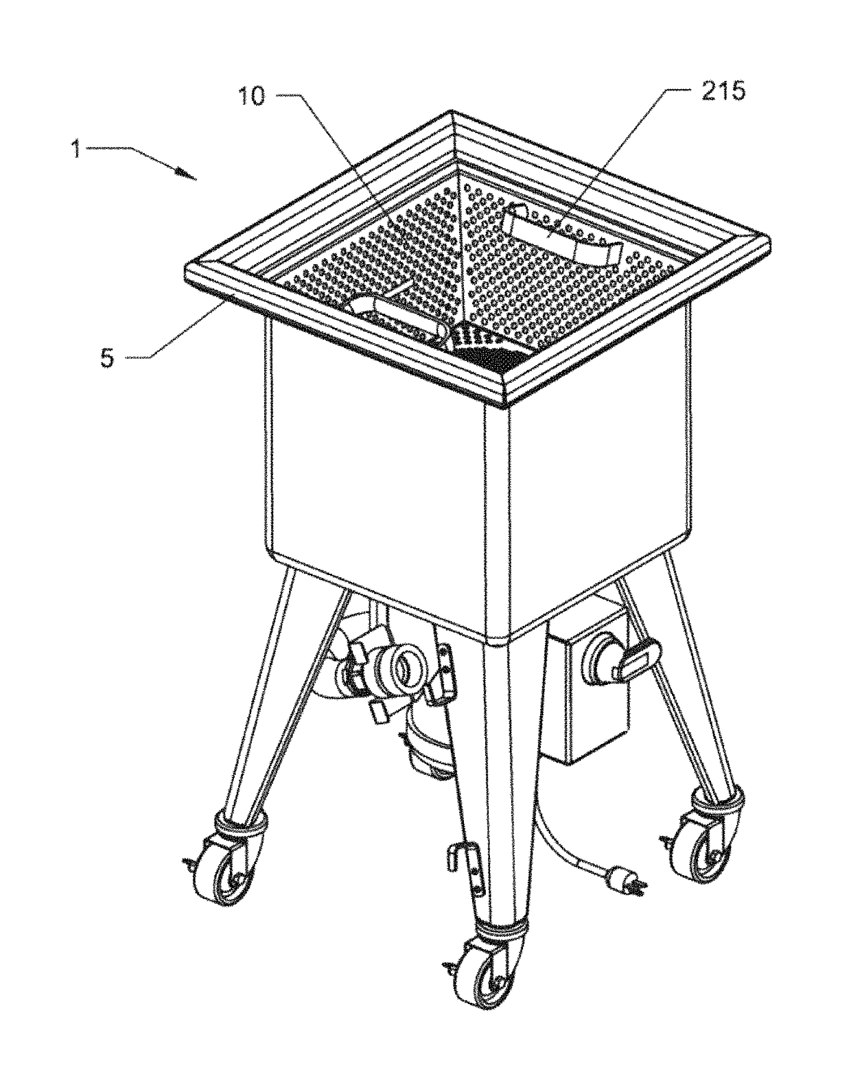
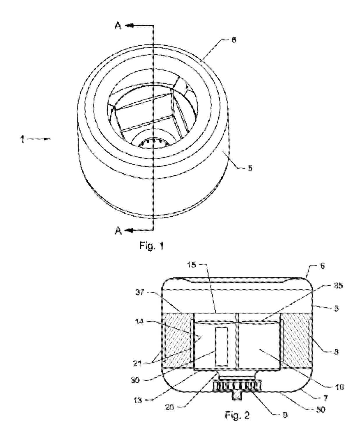
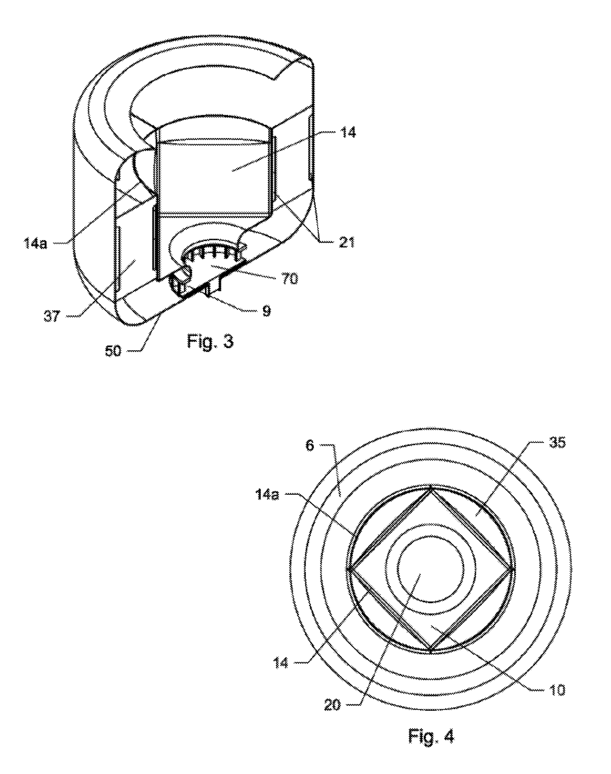
[0047]A method of defrosting items 30 in a defrosting machine 1 is provided. An embodiment of the method includes the following steps. A cavity 10 of the defrosting machine 1 is filled with a defrosting fluid. A fluid level sensor identifies when the fluid level in the cavity 10 has reached a prescribed threshold fluid level. After the fluid reaches the threshold fluid level, a temperature sensor measures the temperature of the defrosting flui...


PUM

PropertyMeasurementUnit
angleaaaaaaaaaa
diameteraaaaaaaaaa
diameteraaaaaaaaaa

Abstract

An apparatus and a method of defrosting frozen items, is provided. The apparatus and method utilizes a fluid flow system and method, such as a fluid-push / pull system in which generally an entire volume of fluid is pushed or pulled through a cavity in which frozen items are located and / or a continuous motion system in which fluid is circulated within a fluid tank of the system.

Description

CROSS-REFERENCE TO RELATED APPLICATIONS[0001]This application claims priority pursuant to 35 U.S.C. 119(e) to U.S. Provisional Patent Application Ser. No. 61 / 843,437 filed Jul. 7, 2013, the entire disclosure of which is incorporated herein by reference.FIELD OF THE INVENTION[0002]The present general inventive concept relates to a defrosting system and method, and more particularly, to an apparatus and a method of utilizing a fluid-push / pull system and / or continuous motion fluid system as part of a defrost system and method.BACKGROUND OF THE INVENTION[0003]Pot and pan washing machines, of the type used in restaurants, institutions and other eating facilities often involve a large wash tank or basin in which water (mixed with detergent, generally a cleaning “fluid”) is circulated within a wash tank to wash the “wares” (i.e. pots, pans, utensils, flatware / silverware, etc.) to provide a washing action. One such machine is described in U.S. Pat. No. 4,773,436 issued to Cantrell et al. (t...

Claims


Application Information

Patent Timeline
Patent Type & Authority Patents(United States)
IPC IPC(8): G01K13/00F25B49/00F25D21/12F25D17/02A23L3/365
CPCA23L3/365
Inventor CANTRELL, JOHNCHURCHILL, MARKLICATA, MICHAELGAST, DAVID
Owner UNIFIED BRANDS
Why Eureka
Try Eureka