Method and device for determining optical properties by simultaneous measurement of intensities at thin layers using light of several wavelengths

a technology of intensities and optical properties, applied in the direction of measurement devices, phase-affecting property measurements, instruments, etc., can solve the problems of insufficient light quality, insufficient light quality, and inability to achieve uniform intensity distribution, so as to achieve significant reduction of data and improve signal quality.

Active Publication Date: 2017-08-15
BIOCOPY HLDG AG
View PDF21 Cites 4 Cited by
  • Summary
  • Abstract
  • Description
  • Claims
  • Application Information

AI Technical Summary

Benefits of technology

[0076]The use of CCD arrays is preferred if a structured, spatially resolved detection of the reflected light rays is to be made in such a way that there results a direct mapping of the light radiated onto the carrier with the thin layer in the form of multiple individual light sources, to each individual irradiated spot on the thin layer. This is especially beneficial when there are various different compounds disposed on the thin layer or coupled to it. It allows the selective detection of the different components in the sample to be analyzed.
[0077]In this way a number of signals are recorded, each originating from the individual spots on the thin layer illuminated by the light source. Then no actual pattern recognition is necessary, the amount of data is significantly reduced and the signal quality is thereby improved.

Problems solved by technology

A disadvantage with all previously used methods is that the system technology on which they are based is characterized by a considerable dependence on the intensity.
The fact that no uniform distribution of intensity could be achieved also had an adverse effect on the reference measurements for the brightness of the light source, at least for such measurements that are to be carried out using so-called multiwell plates.
Here it was found that the quality of the light was only sufficient in the central part of the light field emitted by the light source.
Therefore the sensitivity and the reliability of these methods of measurement were still inadequate, making it difficult to use the methods in practice.
This requires a great deal of work for the evaluation and a correspondingly large amount of time to derive the desired parameters.
The computational complexity is associated with a significant computing time, which makes an evaluation in real time for many samples that are to be analyzed simultaneously very demanding or indeed no longer technically feasible.

Method used


Image

  • Method and device for determining optical properties by simultaneous measurement of intensities at thin layers using light of several wavelengths
  • Method and device for determining optical properties by simultaneous measurement of intensities at thin layers using light of several wavelengths

Examples


Embodiment Construction

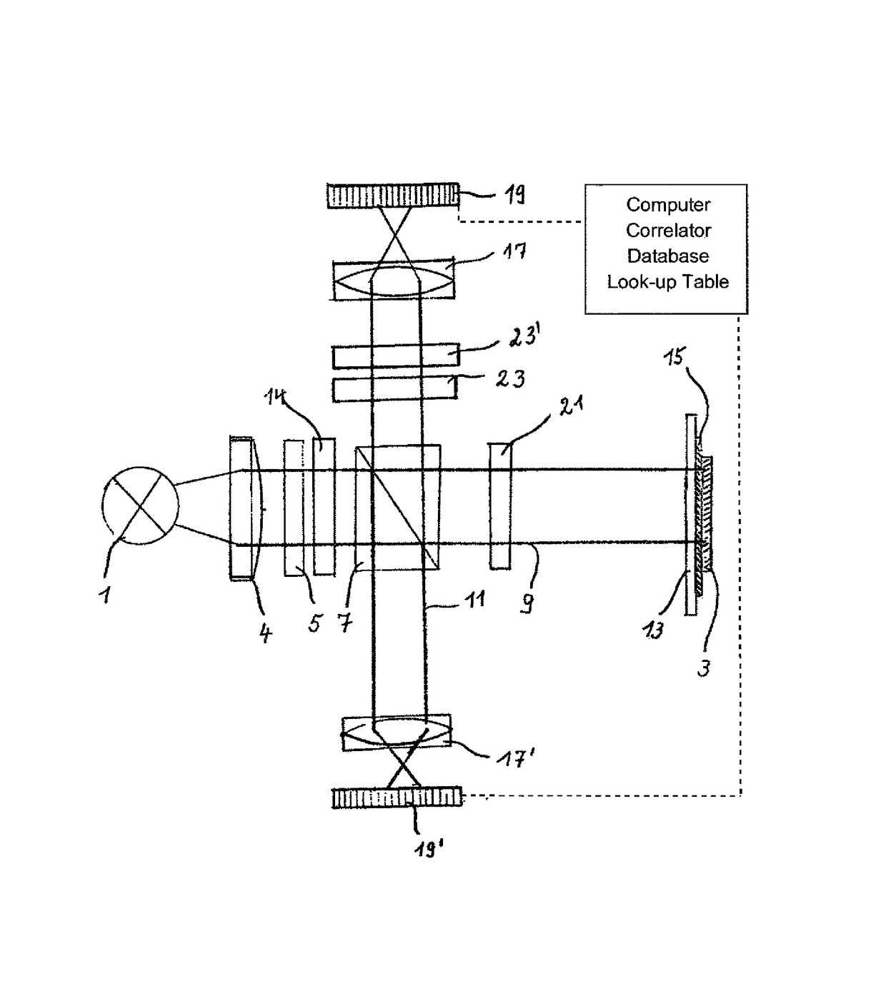
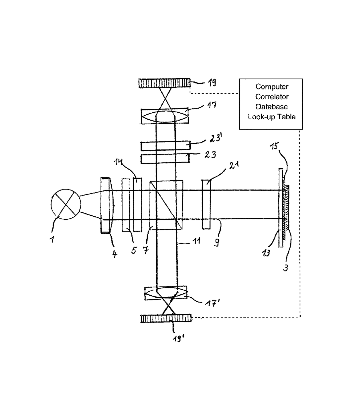
[0084]In FIG. 1, as the only FIGURE, the reference number 1 indicates a light source in the form of an LED light, by means of which a sample 3 to be tested is irradiated vertically. Before this, the light emitted from the LED light passes through a diffuser 4 in the form of a filter, which distributes the light evenly, and a polarizer 5 to produce linearly polarized light. In this way, light of a narrow wavelength range defined by the LED lamp is directed onto the sample 3, by also passing through a polarizing beam splitter 7. The beam splitter 7 divides the light into a measuring beam 9 and a reference beam 11. This test arrangement also allows one to use a classic broadband light source, and to produce the desired narrow wavelength range by using a downstream wavelength filter. Such an optional wavelength filter is provided in FIG. 1 for the purpose of illustration and is indicated there by reference number 14.

[0085]The sample 3 contains an at least partially transparent carrier 1...


PUM

PropertyMeasurementUnit
full width at half maximumaaaaaaaaaa
optical propertiesaaaaaaaaaa

Abstract

In a method for determining optical properties by measuring intensities at a thin layer, light is directed into the thin layer and passes through a beam splitter, which directs a first part of the light onto the thin layer and a second part of the light onto a reference detector. Interference of the first part of the light in the thin layer is detected via a high-resolution detector and forwarded to an evaluating unit, which determines the reflection and/or transmission coefficients, which are correlated with the optical layer thickness through a comparison using at least one database stored in the evaluating unit. The optical layer thickness is obtained as a gray value modification by way of a gray scale value analysis and a conversion factor stored in the at least one data base. A corresponding device and intended uses of the method and device are also described.

Description

CROSS-REFERENCES TO RELATED APPLICATIONS[0001]This application is the U.S. National Stage of International Application No. PCT / EP2011 / 000419, filed Jan. 31, 2011, which designated the United States and has been published as International Publication No. WO 2012 / 103897, pursuant to 35 U.S.C. 119(a)-(d).BACKGROUND OF THE INVENTION[0002]The invention relates to a method and a device for determining optical properties by measuring intensities at a thin layer for the detection of chemical, biochemical, medical and / or physical reactions, binding and / or accretion processes as well as other interactions, as preferred uses, in particular in the field of homeland security.[0003]It is known that one can determine physical, chemical, biochemical or biological processes such as reactions, binding and accretion processes and other forms of interaction, at a thin layer of at least partially optically transparent material, by changing the optical layer thickness. For this, light of at least one spe...

Claims


Application Information

Patent Timeline
Patent Type & Authority Patents(United States)
IPC IPC(8): G01B9/02G01N21/45G01N21/84
CPCG01B9/02G01B9/02024G01N21/45G01N21/8422
Inventor PROLL, GUNTHERPROLL, FLORIAN
Owner BIOCOPY HLDG AG
Why Eureka
Try Eureka