Illumination device and projector

a technology of projector and projection device, which is applied in the direction of projector, optics, instruments, etc., can solve the problems of increasing the thickness of the entire device, the size of the device or the entire device, and the intensity of blowing of cooling air, so as to suppress the effect of an increase in siz

Active Publication Date: 2017-08-15
SEIKO EPSON CORP
View PDF4 Cites 0 Cited by
  • Summary
  • Abstract
  • Description
  • Claims
  • Application Information

AI Technical Summary

Benefits of technology

[0009]According to this configuration, the illumination device includes the plurality of light source devices, the reflective portion, and the cooling device disposed on one side of the reflective portion in the third direction. The one side of the reflective portion in the third direction does not serve as the optical path of the light from the light source device, and is a region that is liable to be a dead space, and therefore, the cooling device can be efficiently disposed. Accordingly, it is possible to provide the illumination device emitting light of high luminance and suppressing an increase in size and the degradation of the plurality of light source devices.Application Example 2
[0030]According to this configuration, the projector include the illumination device described above, and therefore can project a bright image over a long period of time while suppressing an increase in size.

Problems solved by technology

However, since the lamp unit disclosed in JP-A-2013-218101 has a structure in which the four blast fans are respectively stacked on the lamp holders, the lamp unit has problems such as an increase in the size of the device or an increase in the thickness of the entire device.
The sirocco fan has a high discharge pressure of cooling air to be discharged, compared with an axial fan, and therefore can blow the cooling air intensively to a light source in the light source device.

Method used


Image

  • Illumination device and projector
  • Illumination device and projector
  • Illumination device and projector

Examples


modified example

[0123]The embodiment may be modified as follows.

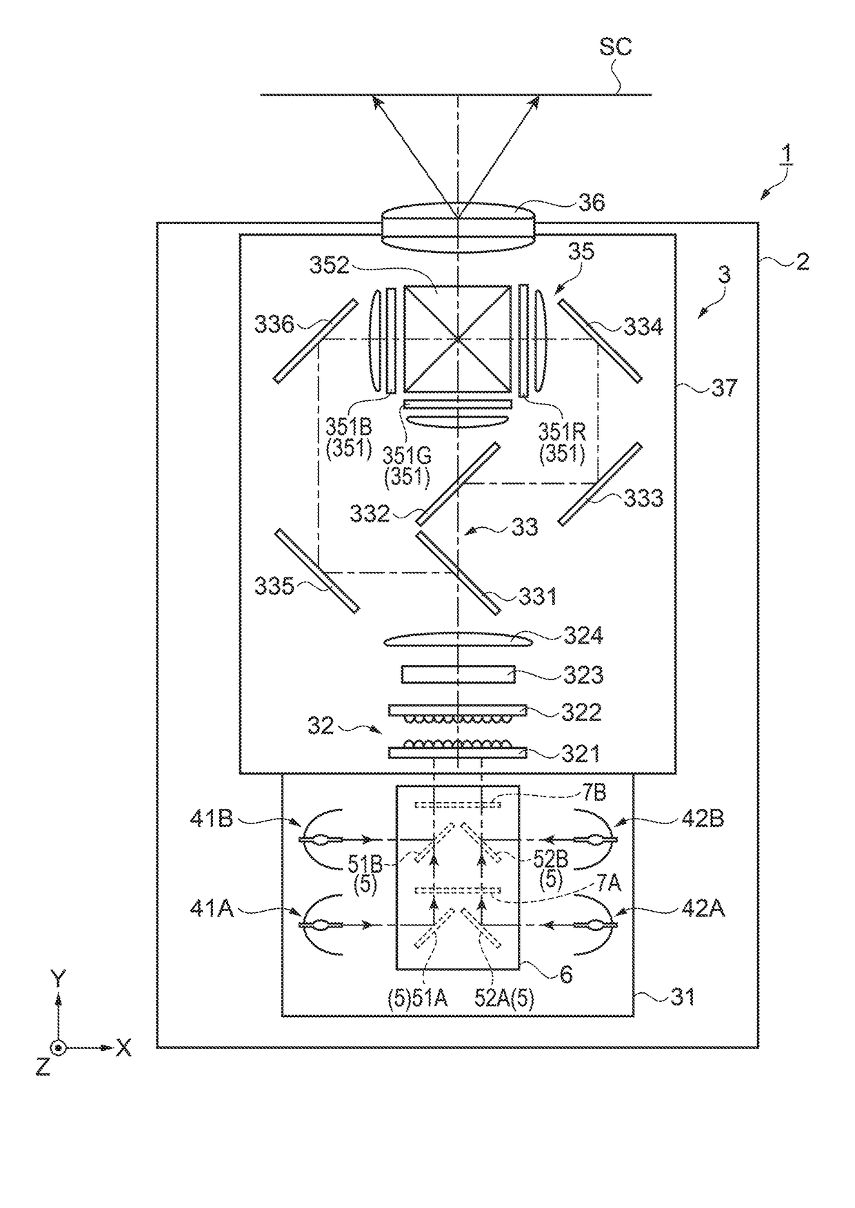
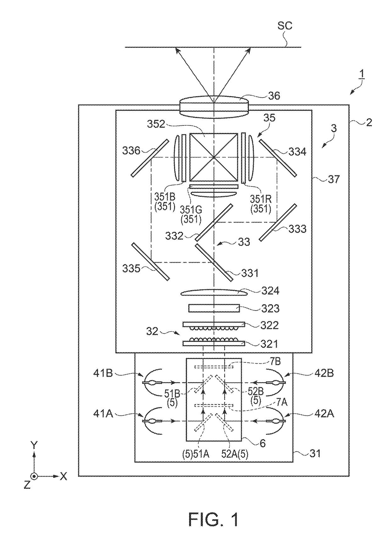
[0124]The illumination device of the embodiment includes the two sets of the first light source device 41A, 41B and the second light source device 42A, 42B emitting light in the first directions opposite to each other. However, the illumination device is not limited to that including two sets but may be an illumination device including one set or three or more sets of the first light source device and the second light source device disposed along the second direction.

[0125]Moreover, the illumination device may have a configuration including three or more odd number of light source devices as long as the illumination device includes at least one set of the first light source device and the second light source device that emit light in opposite directions.

[0126]The illumination device 31 of the embodiment is configured such that the lights emitted by the two sets of the first light source device 41A, 41B and the second light source devic...


PUM


Abstract

An illumination device includes: a first light source device and a second light source device that emit light in directions opposite to each other in a first direction; a reflective portion that is disposed between the first light source device and the second light source device, and reflects the light emitted from the first light source device and the second light source device in a second direction crossing the first direction; and a cooling device that is disposed on one side of the reflective portion in a direction crossing the first direction and the second direction, and blows cooling air to the first light source device and the second light source device.

Description

BACKGROUND[0001]1. Technical Field[0002]The present invention relates to an illumination device and a projector.[0003]2. Related Art[0004]In the related art, a projector that modulates light emitted from a light source in response to image information and projects the modulated light onto a projection surface such as a screen has been known. Moreover, a device including a plurality of light sources for projecting a brighter image and configured to cool the light sources has been proposed (e.g., see JP-A-2013-218101).[0005]The device (lamp unit) disclosed in JP-A-2013-218101 includes: a lamp fan base forming a housing structure; a lamp case including four lamp holders on which four light source lamps are respectively mounted, and movably supported to the lamp fan base; a fan base on which blast fans are placed and which is supported to the lamp fan base; and a duct provided in the fan base and guiding the air from the blast fan to a light-emitting portion of the light source lamp. Fo...

Claims


Application Information

Patent Timeline
Patent Type & Authority Patents(United States)
IPC IPC(8): G03B21/16G03B21/00G03B21/20G03B21/12
CPCG03B21/16G03B21/006G03B21/12G03B21/2013
Inventor TAKIZAWA, TAKAHIROSASAKI, FUMIHIDEHORIKO, YUKIHIRO
Owner SEIKO EPSON CORP
Why Eureka
Try Eureka