Assembly and method of facilitating the cleaning of an endotracheal tube

a technology of endotracheal tube and cleaning method, which is applied in the direction of cleaning process and apparatus, respirator, other medical devices, etc., can solve the problems of unfavorable extension or protrusion of the distal end of the tubular member, and achieve the effect of efficient and reliable way

Inactive Publication Date: 2011-07-28
MOREJON ORLANDO
View PDF18 Cites 30 Cited by
  • Summary
  • Abstract
  • Description
  • Claims
  • Application Information

AI Technical Summary

Benefits of technology

[0014]Accordingly, the handle assembly of the present invention is structured to facilitate the cleaning of the endotracheal tube by assuring that an accurate or predetermined length of the tubular member is inserted into the interior of the endotracheal tube and prevent an “over insertion”. Such an over insertion could result in an undesirable extension or protrusion of the distal end of the tubular member and / or the cleaning assembly from protruding outwardly from the distal open end of the endotracheal tube. As such, once the proper length of the tubular member is determined, it is inserted into the endotracheal tube resulting in the cleaning assembly being disposed in a proper position for expansion into its cleaning orientation. As set forth above, such expansion inflation brings the outer surface of the cleaning assembly into confronting relation with the interior surface of the endotracheal tube and effectively facilitates performance of the cleaning procedure. It is emphasized that the expansion device may be other than an inflation device or inflation syringe as set forth above. Such a non-inflation expansion device should be cooperatively functional with an appropriate cleaning assembly to facilitate the selective expansion of the cleaning assembly into the cleaning orientation.
[0015]Accordingly, the handle assembly of the present invention comprises a body structured to be held by one hand of a user in a manner which allows for the manipulation of the inflation device as well as other components associated with or connected to the body of the handle assembly. Moreover, the body includes a proximal end and a distal end, wherein the elongated tubular member is connected to the distal end. An appropriate connection of the tubular member to the distal end of the body accomplishes fluid communication between the inflation device and the cleaning assembly through at least a portion of the interior of the tubular member. Such fluid communication provides for selective inflation or radial expansion of the cleaning assembly when it is accurately positioned within the interior of the endotracheal tube.
[0018]As such, manipulation of the positioning member will serve to efficiently dispose the restricting portion or stop member into aligned relation and / or confronting engagement with the extremity of the proximal end of the endotracheal tube. Further, the manipulation of the positioning member will cause the stop member to move along the length of the tubular member once the tubular member is connected to the distal end of the body. As more specifically described, the cooperative structuring and operation of the calibration assembly and the tubular member will thereby provide an efficient and reliable way of determining the accurate, predetermined length of the tubular member to be safely inserted within the endotracheal tube in order to properly position the cleaning assembly therein, prior to inflation. Such determination of the inserted length of the tubular member will also prevent the distal end of the tubular member, or cleaning assembly associated therewith, from extending outwardly from the open end of the endotracheal tube.
[0019]Other structural and operative features of the handle assembly include the body having a suction port. The suction port is disposed and structured to removably connect at least a portion of the interior of the tubular member to an appropriate vacuum source, thereby allowing for the removal of watery secretions and other material from the interior of the endotracheal tube by suction. An appropriate opening or access port is disposed or formed in the distal end of the tubular member preferably, but not exclusively, beyond the location of the cleaning assembly to further aid in this removal by suction.
[0023]Accordingly, the structure and method of use of the handle assembly of the present invention, when assembled with the aforementioned operative components, will serve to efficiently and reliably clean the interior of the endotracheal tube while it remains in an operative position within a patient.

Problems solved by technology

Such an over insertion could result in an undesirable extension or protrusion of the distal end of the tubular member and / or the cleaning assembly from protruding outwardly from the distal open end of the endotracheal tube.

Method used


Image

  • Assembly and method of facilitating the cleaning of an endotracheal tube
  • Assembly and method of facilitating the cleaning of an endotracheal tube
  • Assembly and method of facilitating the cleaning of an endotracheal tube

Examples


Embodiment Construction

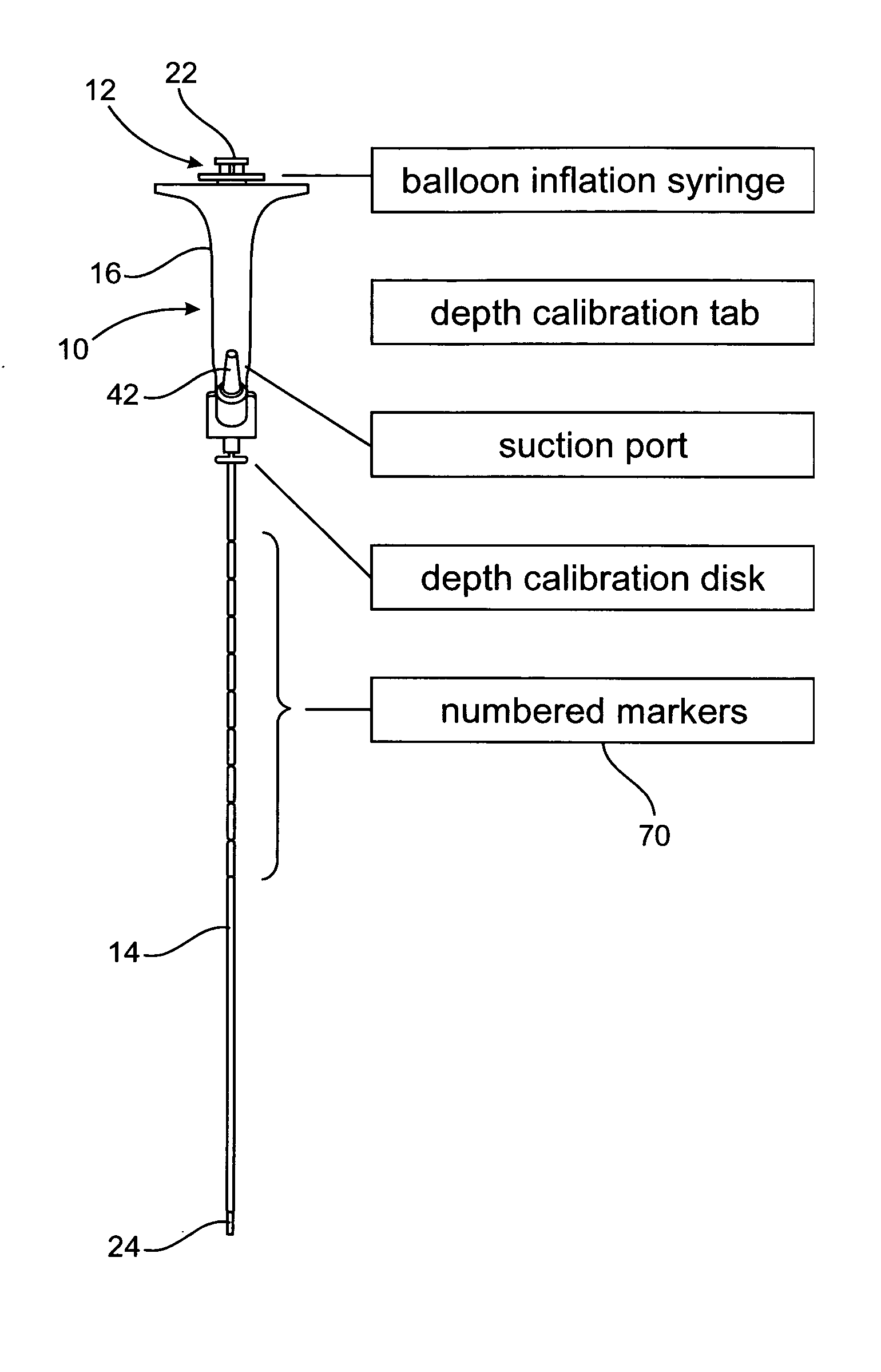
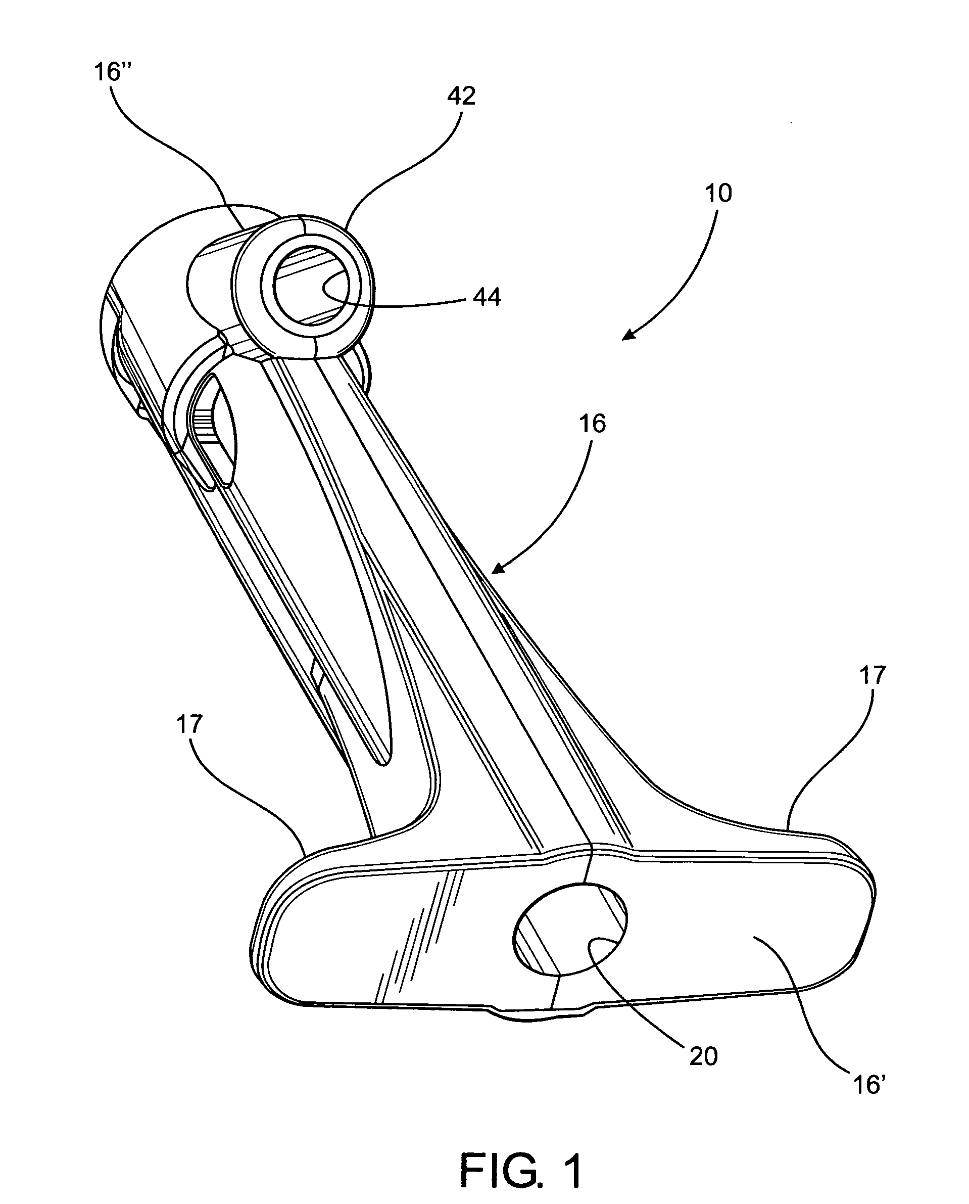
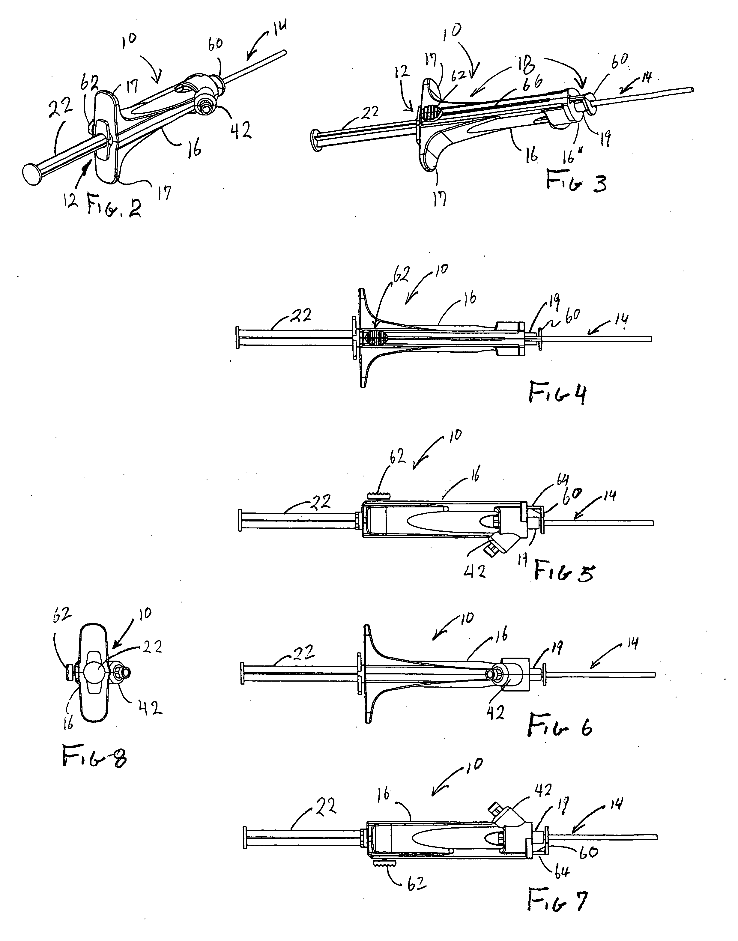
[0041]As shown in the accompanying drawings, the present invention is directed to a handle assembly, generally indicated as 10, which when connected to or assembled with other operative components, facilitates the cleaning of an interior of an endotracheal tube 100, while the endotracheal tube is positioned within a patient. As set forth in greater detail hereinafter, the aforementioned cooperative components with which the handle assembly 10 is assembled and / or connected includes an expansion device generally indicated as 12 and an elongated tubular member or catheter structure 14 represented in an assembled form in FIGS. 2-8, 9A, 9B, 11A, 11B, 12 and 13.

[0042]The handle assembly 10 comprises a body generally indicated as 16 having a generally elongated configuration and being further structured and configured to be held by a hand of a user, as at least partially represented in FIG. 13. As represented the body 16 may be gripped in a manner which facilitates the manipulation of the ...


PUM


Abstract

A handle assembly and method of its use which facilitates the cleaning of the interior of an endotracheal tube. The handle assembly comprises a body structured to be held and manipulated by a hand of a user and is structured to removably retain an inflation device. A tubular member is connected to the body and is dimensioned to be inserted within and pass along an interior length of the endotracheal tube to facilitate the cleaning thereof. A calibration assembly is movably connected to the body and structured to determine an accurate or appropriate length of the tubular member to be inserted within the endotracheal tube to avoid over insertion of the tubular member. A positioning member associated with the calibration assembly is connected to the restricting portion and is movable along the length of the body to position the positioning / stop member adjacent the proximal end of the endotracheal tube for alignment and determination of the accurate length of the tubular member to be inserted.

Description

BACKGROUND OF THE INVENTION[0001]1. Field of the Invention[0002]This invention is directed to a handle assembly and a method of using it to facilitate the cleaning of an interior of an endotracheal tube. A hand held body comprises a calibration assembly which determines the proper length of a tubular member / catheter to be inserted within the endotracheal tube to efficiently accomplish the cleaning procedure. The calibration assembly is manipulated for selective positioning on and relative to the body in order to determine an appropriate length of the tubular member to be inserted within the endotracheal tube to accomplish the cleaning procedure, while preventing the potentially dangerous extension of the tubular member out of the open internal, distal end of the endotracheal tube.[0003]2. Description of the Related Art[0004]Many patients in a hospital and in particular, patients in an Intensive Care Unit (“ICU”) must be fitted with endotracheal tubes to facilitate their respiration....

Claims


Application Information

Patent Timeline
Patent Type & Authority Applications(United States)
IPC IPC(8): B08B9/04A61M16/04
CPCA61M2209/04A61M16/04A61M16/0486
Inventor MOREJON, ORLANDO
Owner MOREJON ORLANDO
Why Eureka
Try Eureka