Highly-efficient freezing apparatus and highly-efficient freezing method

a technology of high-efficiency freezing and equipment, which is applied in the field of high-efficiency freezing equipment and highly-efficient freezing methods, can solve the problems of affecting the quality of frozen materials, so as to prevent the coarseness of ice crystals and prevent the destruction of cells, and prevent the effect of cell destruction

Inactive Publication Date: 2005-01-13
ABI
View PDF13 Cites 31 Cited by
  • Summary
  • Abstract
  • Description
  • Claims
  • Application Information

AI Technical Summary

Benefits of technology

[0011] In order to accomplish these objects, the inventor of the present invention has conducted intensive research on a method for preventing the destruction of cells in materials in freezing. As a result, the inventor discovered that it is effective in preventing the coarseness of ice crystals and the destruction of the cells to quickly cool the maximum ice crystallization temperature range, in which ice crystals grow at a high rate, and to suppress the nucleation of ice crystals. The inventor also discovered through further continued research that, application of an oscillating electric field and / or magnetic field to an object to be frozen suppress the nucleation of ice crystals, so that supercooling can be achieved without nucleation of ice crystals down to −10° C. In particular, the inventor has reached a conclusion that it is effective in preventing the nucleation of ice crystals to apply an oscillating electric field of variable frequency in the range of 50 Hz to 5 MHz.
[0012] Furthermore, the inventor discovered that, by simultaneously applying an oscillating electric field and a magnetic field to the object, the free water in the object hydrates with protein and carbohydrate, which are ground substances in food and organisms, to change into bound water forming molecules of hydrated higher order structures. Consequently, the inventor found that the free water is reduced, so that the probability of ice crystallization decreases. Thus, the nucleation of ice crystals can further be prevented.
[0013] Under the idea that it is important to apply a strong, uniform variable magnetic field to the object to be frozen in order to prevent the nucleation of ice crystals, the inventor has conducted intensive research on variable magnetic field-generating means capable of generating a strong, uniform variable magnetic field. The intensity of a magnetic field decreases in inverse proportion to the square of the distance from a magnetic field source. The research has been conducted according to the concept of disposing a variable magnetic field source close to an object to be frozen (hereinafter may be referred to as the object) as much as possible in order to obtain a strong, uniform variable magnetic field. As a result, the inventor found that it is effective to dispose a plurality of variable magnetic field sources in parallel, in series, or crosswise along a holder holding the object so as to be across the holder or so as to surround or sandwich the holder.
[0014] The inventor also found that addition of ionic air flow to cold air for cooling the object accelerates heat transfer to remarkably increase the cooling rate of the object.

Problems solved by technology

However, known frozen storage cannot perfectly prevent changes in color tone of frozen materials, deterioration in taste, and occurrence of dripping.
More specifically, it cannot prevent deterioration of the quality or freshness due to, for example, dripping resulting from thawing.
If the ice crystals grow coarse, the cells of the materials are destructed.
In foodstuffs and food products, and so forth, once the cells of the material are destructed, dripping, which makes it difficult to restore the organisms to the original state, occurs while the material is thawed.
The cooling rate of the inner side of the frozen material is determined by heat transfer from the surface, so the frozen layer in the surface layer interferes the heat transfer to the inner side, thus the cooling of the inner side of the frozen material is delayed.
Consequently, the coarseness of the ice crystals disadvantageously occurs in the inside of the frozen material; hence, the coarseness of the ice crystals is not prevented.
In some types of food, however, the destruction of the cells cannot be completely prevented even by this technique, and quality degradation occurs undesirably in the food frozen.

Method used


Image

  • Highly-efficient freezing apparatus and highly-efficient freezing method
  • Highly-efficient freezing apparatus and highly-efficient freezing method
  • Highly-efficient freezing apparatus and highly-efficient freezing method

Examples


example 1

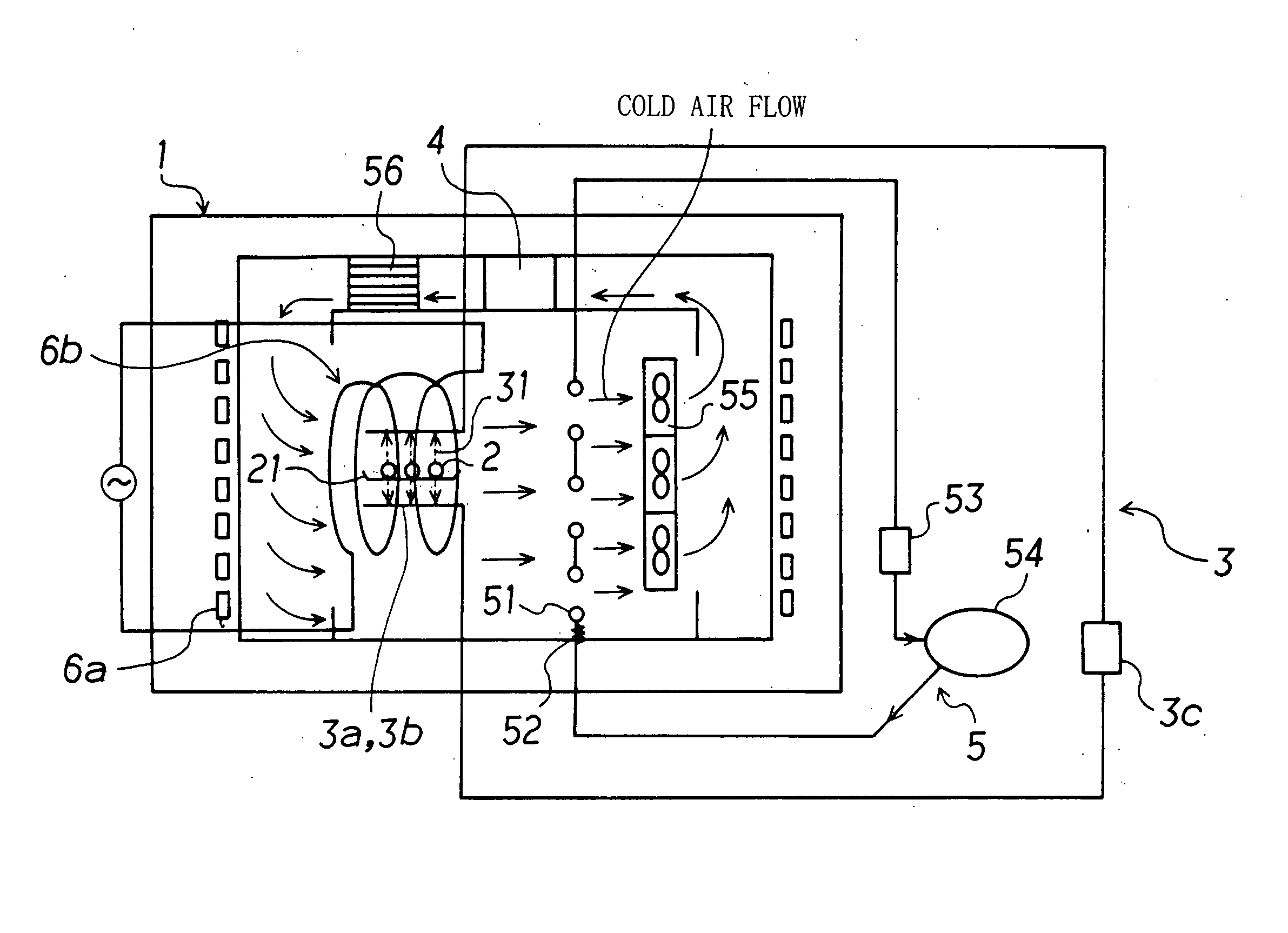
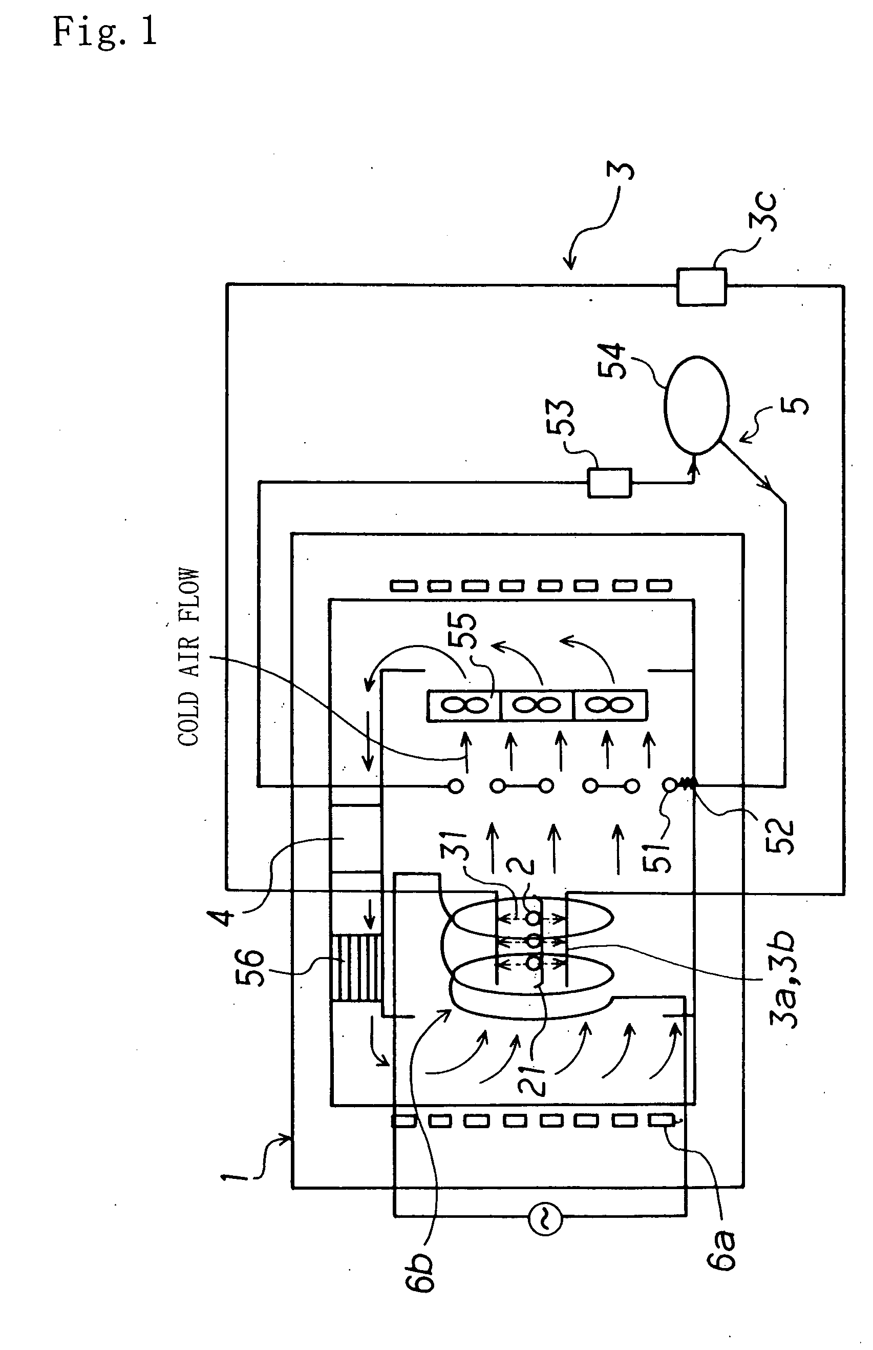
[0125] In use of the rack-type freezer shown in FIG. 1 being the high-functional freezing apparatus of the present invention, raw chicken meat and tuna fish placed as the objects 2 on the holder 21 and accomodated in the internal space of the freezer 1 were frozen by being subjected to the action of the freezing means 5. The internal walls of the freezer 1 were provided with a material capable of absorbing far infrared rays, silica-alumina-iron oxide ceramic in this example. The specifications of the freezing apparatus used were: dimensions, 1.5 m in height by 1.5 m in width by 2.5 m in length; freezing compressor, 10 HP; cooling medium, R22.

[0126] For freezing, the oscillating electric field-generating means 3 applied an oscillating electric field; further a permanent magnet serving as the static magnetic field-generating means 6a and a dielectric coil serving as the variable magnetic field-generating means 6b applied a static magnetic field and a variable magnetic field; further ...

example 2

[0136] A variable magnetic field was generated with a uniform variable magnetic field generator including the electromagnetic coil units 61 disposed in parallel in the longitudinal direction of the rack-type holder 211, as shown in FIG. 4. Four electromagnetic coil units 61 were disposed in parallel in the longitudinal direction of the rack-type holder 211. Each electromagnetic coil unit 61 comprised a rectangular ring-shaped plastic base 611 of 1.2 m in length by 0.7 m in width, having a case-like, U-shaped section with a bore-size of 4 cm×4 cm and an electromagnetic coil 612 formed of 600 turns of copper wire 612a coated with a polyimide resin, wound around the coil base. The electromagnetic coil 612 was subjected to caulking. Then, a cover was bonded to the case-shaped base with an adhesive and, thus, the electromagnetic coil unit containing the electromagnetic coil was completed.

[0137] A coil current of 1 A being an alternating current with a commercial frequency of 50 Hz was p...

example 3

[0141] A variable magnetic field was generated with a uniform variable magnetic field generator including a plurality of electromagnetic coil units 61 disposed in parallel in the moving direction of the holder (net conveyer belt 212), as shown in FIG. 5. Electromagnetic coil units 61 were disposed above and below the net conveyer belt 212 of 1 m in width by 10 m in length so that each member of a pair of the electromagnetic coil units is separated by the net conveyer belt 212 with a distance of 10 cm from the net conveyer belt 212. Forty pairs of electromagnetic coil units 61 were disposed along the moving direction of the net conveyer belt 212 at intervals of 20 cm. Each electromagnetic coil unit 61 comprised a rectangular ring-shaped coil base made by plastics of 1.0 m in length by 0.6 m in width, having a thickness of 4 cm and an electromagnetic coil formed of 600 turns of copper wire coated with a polyimide resin, wound around the coil base. The electromagnetic coils were subjec...


PUM


Abstract

An object accommodated in an internal space of a freezer is quickly cooled to a predetermined temperature with preventing water from freezing while an oscillating electric field of, preferably, a variable frequency in the range of 50 Hz to 5 MHz and / or a magnetic field are applied to the object, or further ionic air is added to clod air, and subsequently the object is instantaneously frozen at the predetermined temperature. Preferably, the magnetic field is a static magnetic field and / or a variable magnetic field.

Description

TECHNICAL FIELD [0001] The present invention relates to methods for freezing foodstuffs, food products, organisms, and other materials, and particularly to a freezing apparatus for producing highly fresh, high-quality frozen products and a freezing method in the freezing apparatus that can maintain the freshness of the material while preventing the destruction of the cells of the material. [0002] High-performance freezing herein refers to a process producing highly fresh, high-quality frozen product while preventing the destruction of the cells of the material to maintain the freshness. [0003] The present invention also relates to a freezing apparatus for frozen products and refrigerated or fridge-frozen preserves, such as those of foodstuffs, food products, and organisms, and particularly to a variable magnetic field generator capable of uniformly applying a variable magnetic field to objects to be frozen. BACKGROUND ART [0004] In order to preserve foodstuffs, food, organisms, and ...

Claims


Application Information

Patent Timeline
Patent Type & Authority Applications(United States)
IPC IPC(8): A23L3/32A23L3/36F25B21/00F25D23/12F25D11/04F25D13/00F25D13/06F25D17/04
CPCA23L3/32A23L3/361F25D2400/30F25D13/06F25D17/042A23L3/363
Inventor OWADA, NORIO
Owner ABI
Why Eureka
Try Eureka