
Metallic color image forming apparatus and metallic color image forming method

a technology of image forming apparatus and metallic color, which is applied in the direction of electrographic process apparatus, instruments, optics, etc., can solve the problem that it is not realistic for the user to prepare various kinds of toner

Inactive Publication Date: 2017-09-05
KK TOSHIBA +1
View PDF11 Cites 94 Cited by
  • Summary
  • Abstract
  • Description
  • Claims
  • Application Information

AI Technical Summary

Benefits of technology

The patent describes an image forming apparatus and method that can print metallic color using toner containing metallic pigment. The apparatus includes a plurality of electrostatic latent image forming sections, developing sections, transfer section, and fixing section. The apparatus can also have a document image reading device and an automatic document feeder. The technical effect of this patent is to provide an improved method for printing metallic color using a conventional image forming apparatus.

Problems solved by technology

Further, it is not realistic for the user to prepare various kinds of toner for each color tone of the metallic color and to exchange the toner for each color tone.

Method used


Image

  • Metallic color image forming apparatus and metallic color image forming method
  • Metallic color image forming apparatus and metallic color image forming method
  • Metallic color image forming apparatus and metallic color image forming method

Examples


first embodiment

A First Embodiment

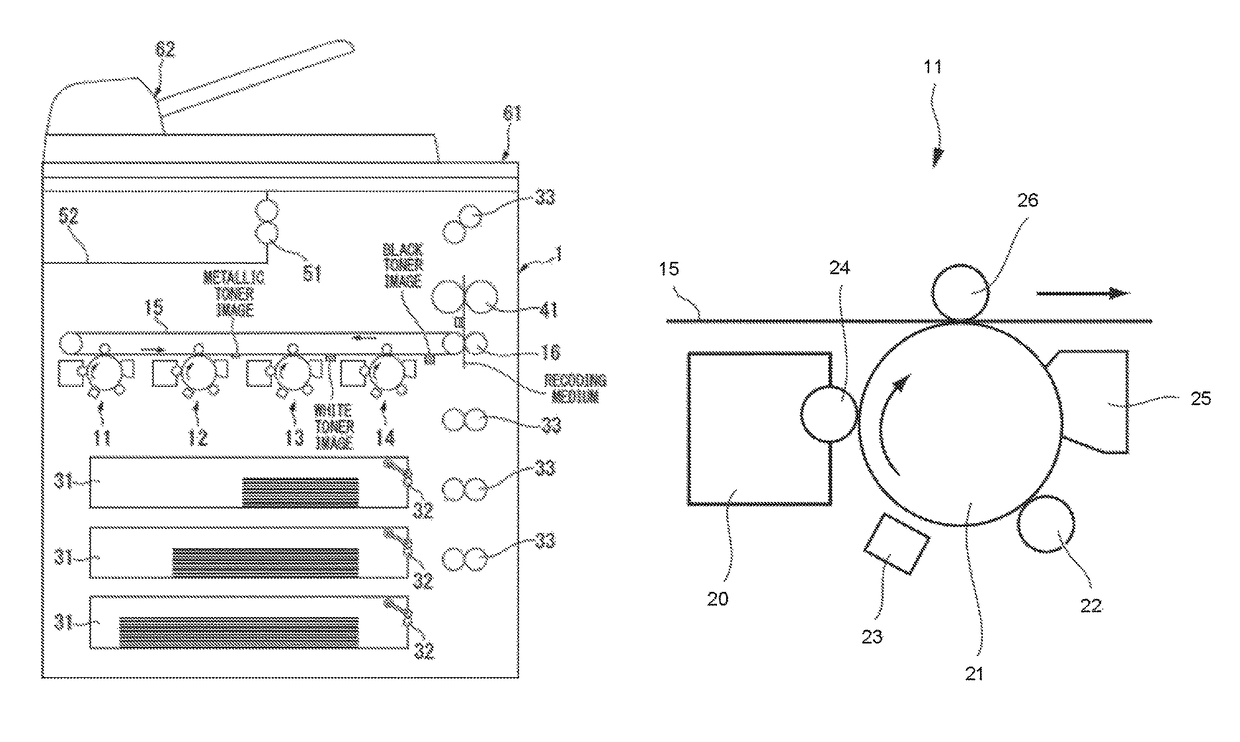
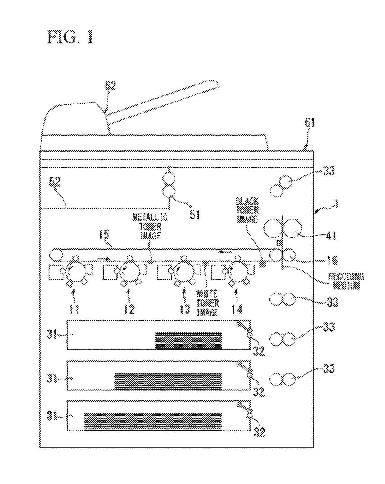
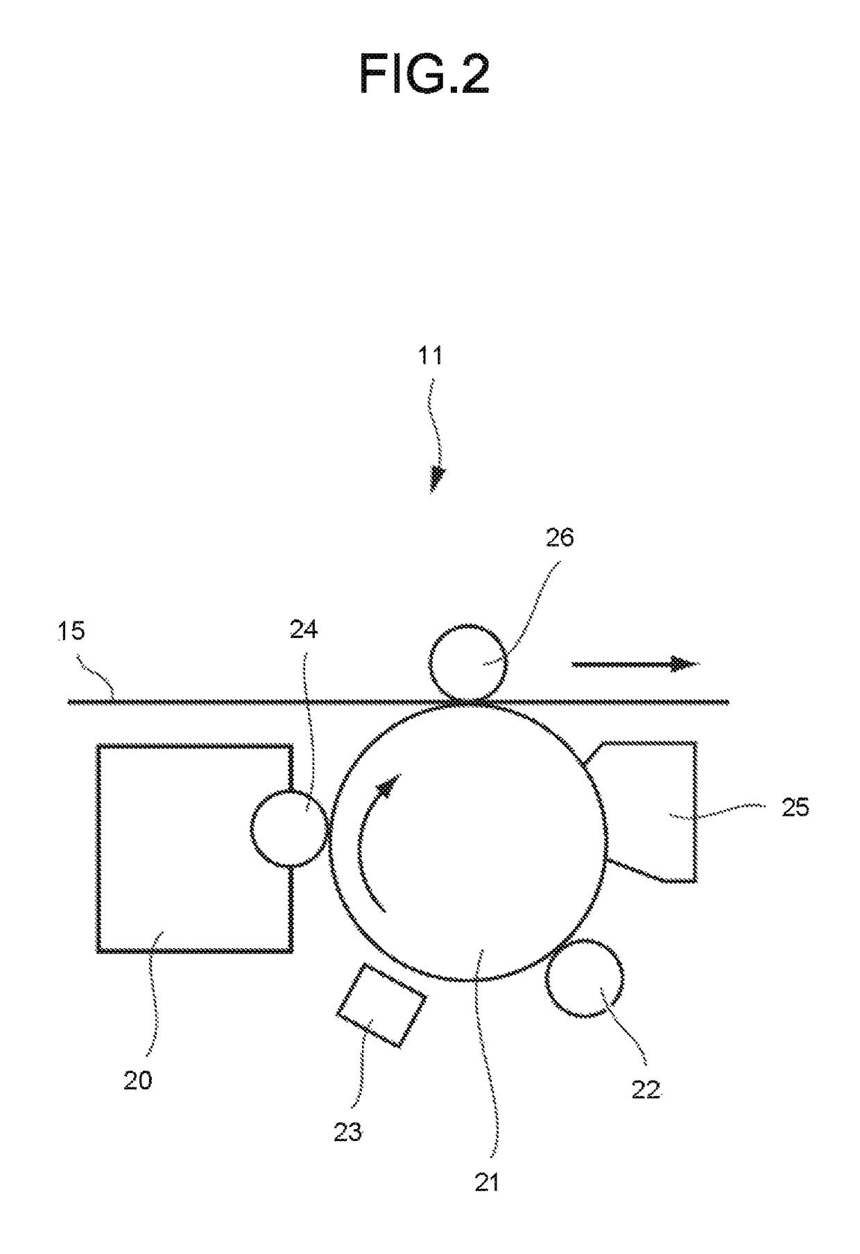
[0009]FIG. 1 is a schematic cross-sectional view illustrating an image forming apparatus 1 according to the present embodiment. FIG. 2 is an enlarged cross-sectional view schematically illustrating a first image generation unit 11 in FIG. 1.

[0010]As shown in FIG. 1, the image forming apparatus 1 according to the present embodiment comprises a first image generation unit 11, a second image generation unit 12, a third image generation unit 13, a fourth image generation unit 14, a transfer belt 15, a secondary transfer roller 16, a cassette 31, a recording medium feed roller 32, a recording medium conveyance roller 33, a fixing roller 41, a recording medium discharge roller 51, a discharge tray 52, a document image reading device 61 and an automatic document feeder 62.

[0011]Each component of the image forming apparatus 1 is described below.

[0012]The document image reading device 61 and the automatic document feeder 62 are arranged at the upper portion of the image for...

second embodiment

A Second Embodiment

[0066]The second embodiment is described below.

[0067]The present embodiment is a modification of the first embodiment described above.

[0068]The image formed by the image forming apparatus 1 according to the present embodiment is not limited to the copy of the image read by the document image reading device 61. The image formed by the image forming apparatus 1 may be, for example, an image pattern formed through an operation on an operation screen which will be described later, a pattern created on a computer, or a photograph captured by a digital camera. In this case, an image generation operation is carried out in the first image generation unit 11, the second image generation unit 12, the third image generation unit 13 and the fourth image generation unit 14 based on the electric signal sent from a computer and the like.

[0069]The image forming apparatus 1 according to the present embodiment may include a function of setting the color concentration of the image, ...

example 1

[0109]The image based on the toner having metallic color tone is printed on the image printed on the printing paper with the white toner.

[0110]As a result, an image having bright metallic color tone is formed.


PUM


Abstract

In accordance with one embodiment, an image forming apparatus forms a metallic toner image with the toner having metallic color tone. The plurality of developing sections includes either or both of a developing section for forming a black toner image with the black toner and a developing section for forming a white toner image with the white toner. The plurality of developing sections is provided with one or more than two developing sections for forming a metallic toner image with the toner having metallic color tone.

Description

CROSS-REFERENCE TO RELATED APPLICATIONS[0001]This application is a Continuation of application Ser. No. 14 / 312,784 filed on Jun. 24, 2014, the entire contents of which are incorporated herein by reference.FIELD[0002]Embodiments described herein relate generally to an image forming apparatus and an image forming method.BACKGROUND[0003]From a point of decoration improvement, toner containing metallic pigment has come into use in an image forming apparatus.[0004]However, in a case of printing metallic color using conventional image forming apparatus, if a user desires to change the color tone of the metallic color, it is necessary to prepare the toner for each color tone. Further, it is not realistic for the user to prepare various kinds of toner for each color tone of the metallic color and to exchange the toner for each color tone.BRIEF DESCRIPTION OF THE DRAWINGS[0005]FIG. 1 is a schematic cross-sectional view illustrating an image forming apparatus according to a first embodiment; ...

Claims


Application Information

Patent Timeline
Patent Type & Authority Patents(United States)
IPC IPC(8): G03G15/01G03G15/00
CPCG03G15/0121G03G15/6585G03G2215/0132
Inventor KABAI, TAKAHITO
Owner KK TOSHIBA
Learn More