
Eureka
For R&D, Eureka makes reading and utilizing patents & technical documents easy.
Eureka AIR
Designed for self-driven R&D workflows. Generate viable solutions, solve complex R&D challenges, empower your innovation with AI.

Eureka Materials
Designed for material experts only. Revolutionize your material R&D, from search, analyze, to developing new materials.

TechResearch
Generate reliable direction feasibility study reports for your R&D in just a few steps.

TechSeek
Discover and master advanced knowledge NOW. Basics, ideas, possibilities, all at once.

TechMind
As an expert in R&D Theories, TechMind can generates customized viable solutions instantly.

TechRisk
Analyze your overall solution with one click, know your potential R&D risks in advance.

TechMonitor
Get weekly tech updates, stay abreast of the latest tech innovations and key insights.
Camera camouflage device
- Summary
- Abstract
- Description
- Claims
- Application Information
AI Technical Summary
Benefits of technology
Problems solved by technology
Method used
Image

Examples
first embodiment
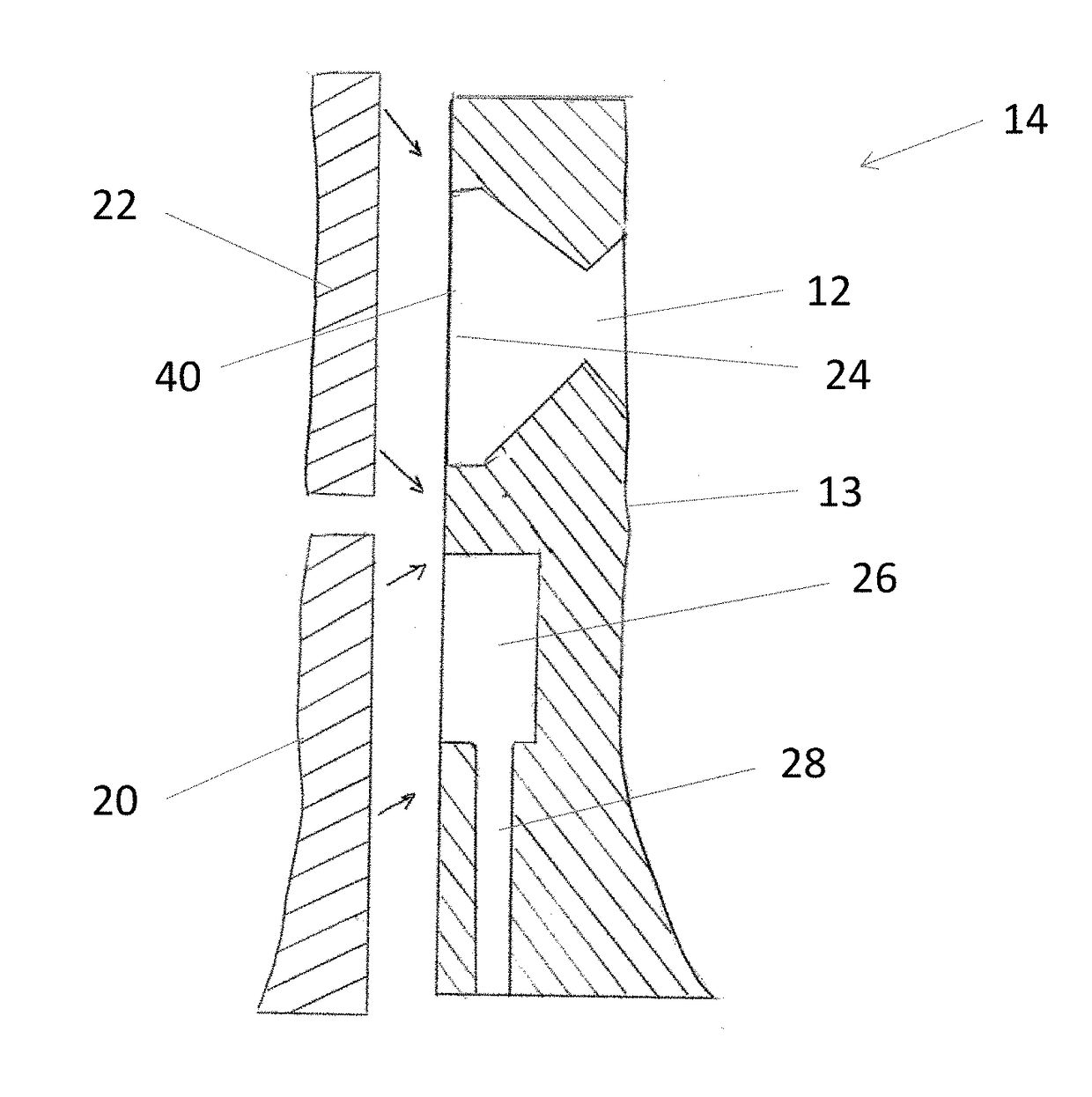
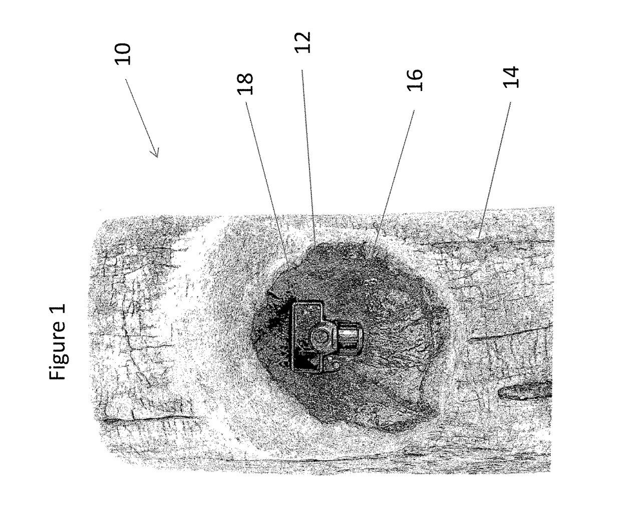
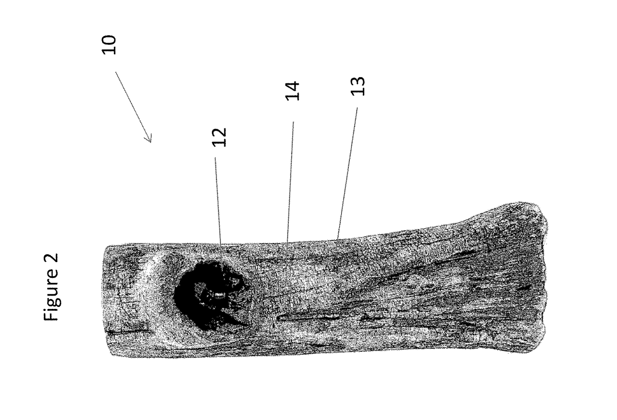
[0048]the present invention is a free-standing tree stump camera camouflage device 10, as shown in FIGS. 1-15. The device 10 has a front cover 14 and a back covers 20 and 22. As shown in FIGS. 1, 2 and 5, the front cover 14 has a front side 13, a back side 15 and an opening 12 therethrough. The front side 13 has a camouflage surface 11 and a front opening 9 that fluidly connects with the opening 12. The back side 15 has a camera compartment 24 that fluidly connects with the opening 12, a camera compartment back opening 40 that fluidly connects with the camera compartment, and a locking compartment 26. In a preferred embodiment, the camera compartment and the locking compartment are one compartment.
[0049]As shown in FIGS. 6 and 7, the back cover can be two or more covers, a back bottom cover 20 and a back top cover 22. In a preferred embodiment, the cover is one piece. Each back cover has an inner side 21 and an outer side 23. The outer side 23 has a camouflage surface 11. The inner ...
second embodiment
[0056]the present invention, as shown in FIGS. 16 to 30, is a tree-mounted knothole device 110 is used to camouflage and to secure a camera to a tree trunk. The device 110 can be made of polyurethane plastic, urethane foam, plywood, tree bark, tree parts, or other materials. The device 110 has a knothole 114. As shown in FIGS. 1, 2 and 5, the knothole 114 has a perimeter 108, a front opening 109, a front side 113 and a back side 115. The front side 113 has a camouflage surface 111 and an opening 112. The back side 115 has a camera compartment 124 that fluidly connects with the opening 112.
[0057]As shown in FIGS. 18, 26, 27 and 28, the camera compartment is configured to removeably mount a camera. In a preferred embodiment, on the back side 115 of the knothole 114, a removeable insert 116 is placed that is designed to securely nest in the camera compartment 124. When the insert 116 is mounted in the camera compartment 124 it has an insert opening 120 that communicates fluidly between...
PUM
 Abstract
Description
Claims
Application Information
 - R&D Engineer
- R&D Manager
- IP Professional
- Industry Leading Data Capabilities
- Powerful AI technology
- Patent DNA Extraction
Browse by: Latest US Patents, China's latest patents, Technical Efficacy Thesaurus, Application Domain, Technology Topic, Popular Technical Reports.
© 2024 PatSnap. All rights reserved.Legal|Privacy policy|Modern Slavery Act Transparency Statement|Sitemap|About US| Contact US: help@patsnap.com