Compressed air supply unit, compressed air supply system, and vehicle, in particular passenger car, having a compressed air supply unit

a technology of compressed air supply and compressed air, which is applied in the direction of mechanical equipment, transportation and packaging, and separation processes, etc., can solve the problems of high air consumption and accumulator operation, and achieve the effect of improving air drying

Active Publication Date: 2017-09-19
ZF CV SYST EURO BV
View PDF21 Cites 5 Cited by
  • Summary
  • Abstract
  • Description
  • Claims
  • Application Information

AI Technical Summary

Benefits of technology

[0009]The fundamental approach to achieving a lengthened dryer bed by means of an arrangement of spaces through which there is to be flow can be used to increase the dryer performance of an air dryer arrangement. Nonetheless, the arrangement of spaces through which there is to be flow can still be improved, inter alia, to limit a pressure loss and to achieve a compact arrangement. It is considerably more advantageous for the design of an air dryer arrangement if a drying container of the air dryer arrangement is formed by means of a container outer wall and a partition along a longitudinal extent of the drying container, wherein the partition divides an internal space delimited by the container outer wall into a first and a second chamber, which are nevertheless linked by a pneumatic link. Improved air drying can be achieved because the partition adjoins the container outer wall along the longitudinal extent and subdivides the internal space of the drying container into a first chamber and a second chamber, which are arranged adjacent to one another, wherein the first and the second chamber are delimited by the partition and the container outer wall. This has the advantage of a relatively compact and robust construction combined with improved dryer performance.
[0035]In other words, the constructional unit comprising the air compressor, the motor and the drying container can form an approximately U-shaped housing arrangement having a first and second leg and a base. With this approximately U-shaped housing arrangement, the motor extends along the first leg and the drying container extends along the second leg and the air compressor extends along the base. Furthermore, the valve arrangement can be arranged on a side of the base opposite the legs. To this extent, the connection plane extends substantially along the base. This arrangement is of particularly compact and simple construction and is easy to assemble. Moreover, the individual components of the constructional unit—i.e., the air compressor, the motor, the drying container and the valve arrangement—can be designed, manufactured or purchased separately according to requirements and can be supplemented or replaced in a modular fashion.

Problems solved by technology

The compact and pressure-resistant design of the drying container supports the rapid venting cycles that occur in this use and the high air consumption and accumulator operation.

Method used


Image

  • Compressed air supply unit, compressed air supply system, and vehicle, in particular passenger car, having a compressed air supply unit
  • Compressed air supply unit, compressed air supply system, and vehicle, in particular passenger car, having a compressed air supply unit
  • Compressed air supply unit, compressed air supply system, and vehicle, in particular passenger car, having a compressed air supply unit

Examples


Embodiment Construction

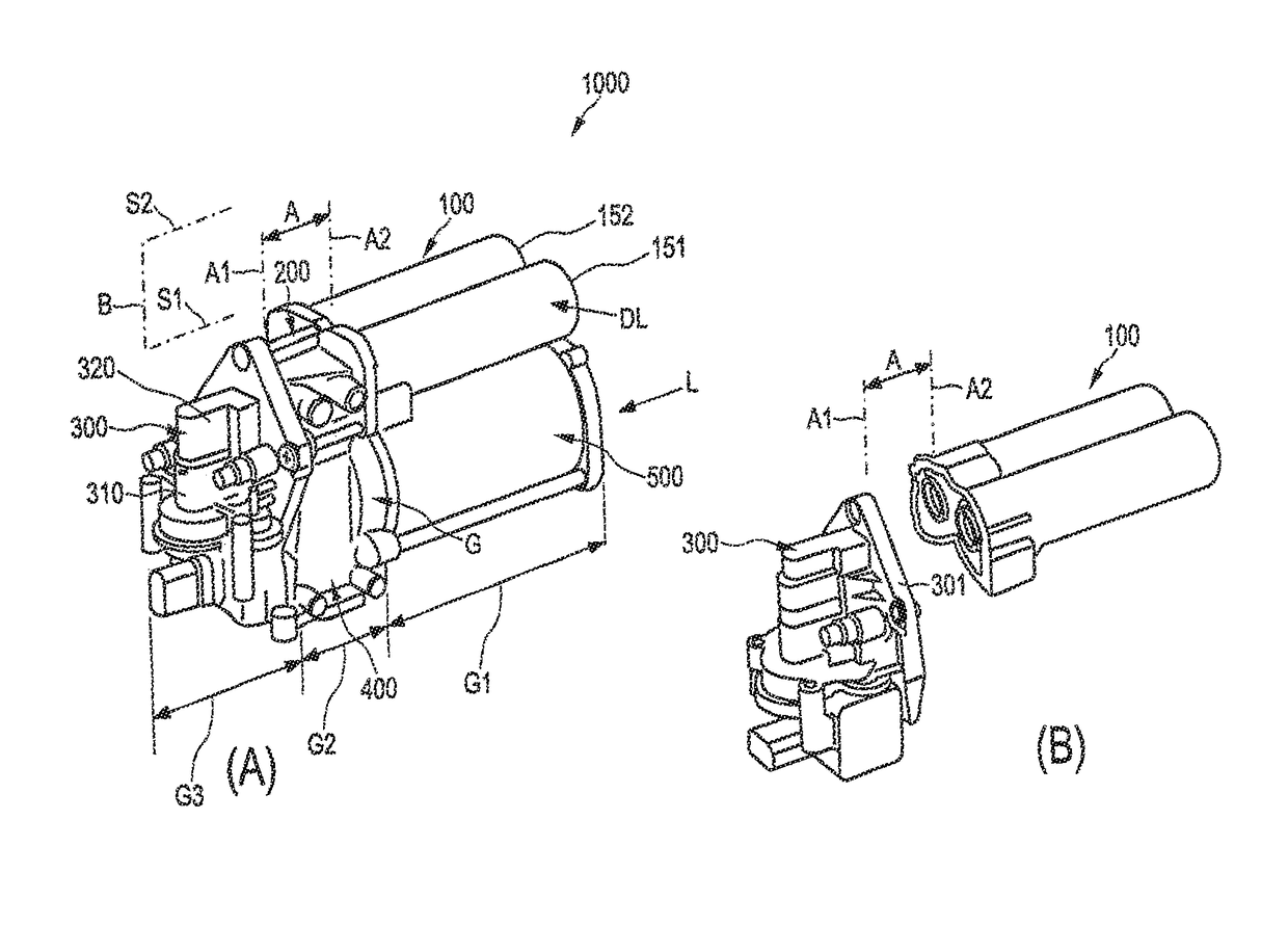
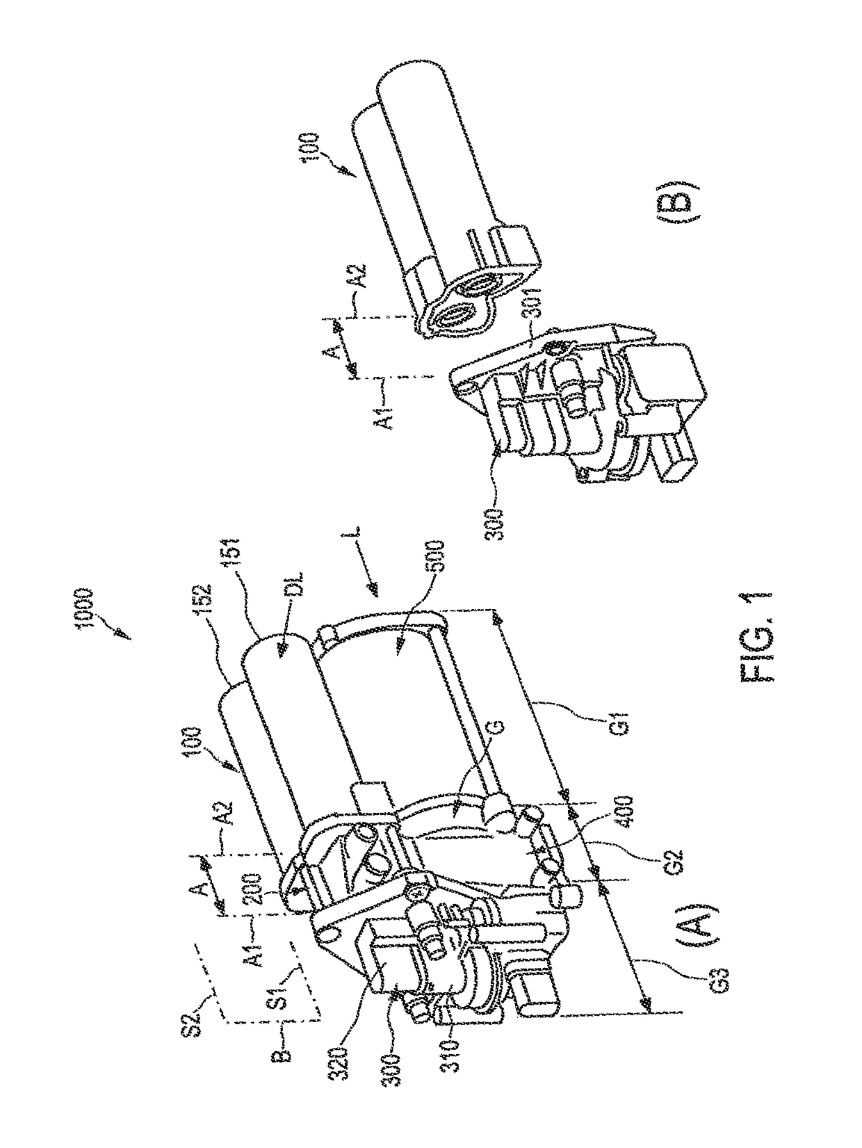
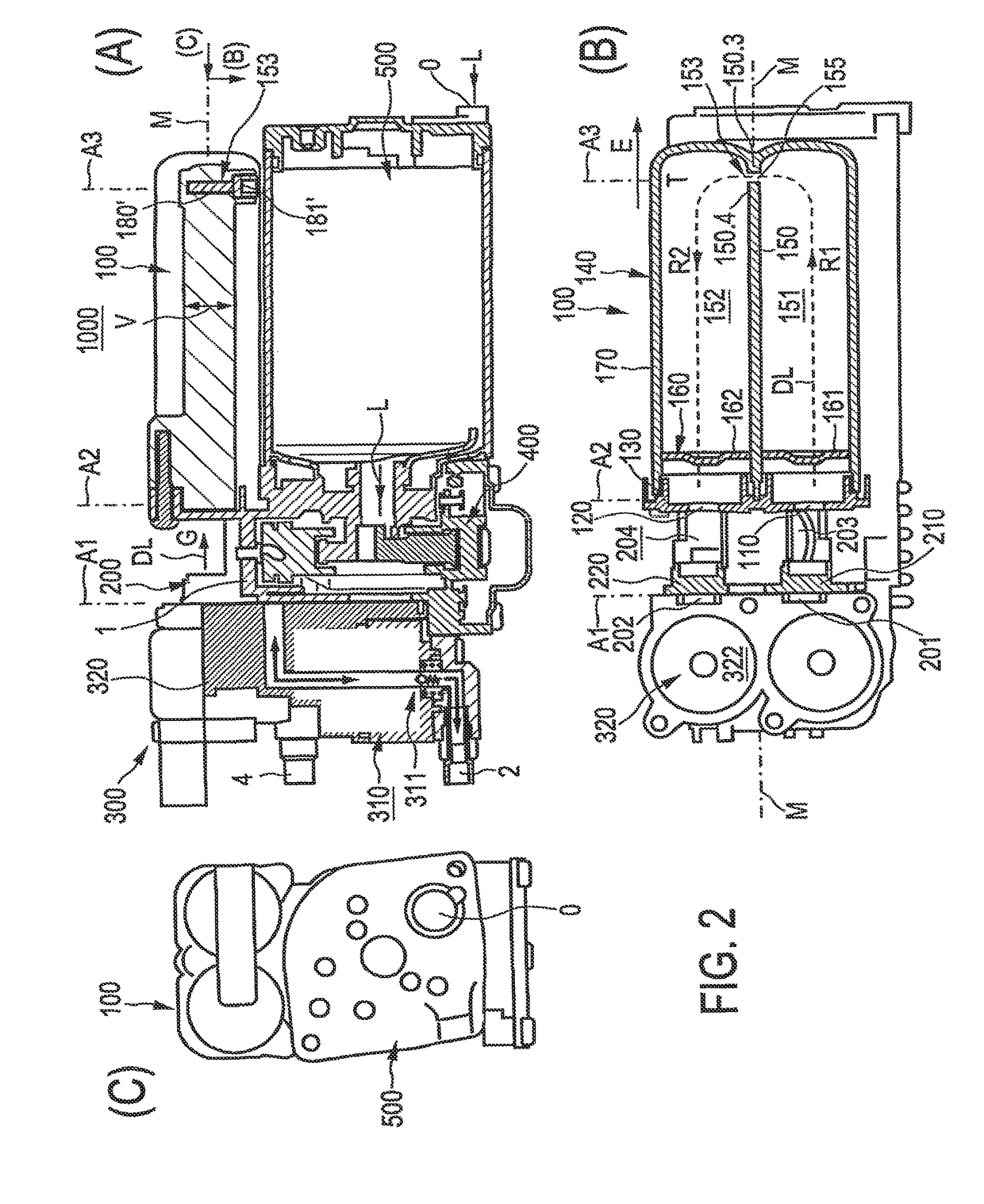
[0152]FIG. 1(A) is a perspective view of a compressed air supply unit 1000 designed for supplying a pneumatic unit 1001 (see also FIG. 3) in the form of an air suspension unit of a passenger vehicle. Referring to FIG. 1, the compressed air supply unit 1000 has a motor 500 for driving an air compressor 400 designed as a dual compressor. Air L to be compressed is fed to the air compressor 400 past the motor 500 and, from there, is fed as compressed air to a main pneumatic line 200, which is shown symbolically in FIG. 1 and in greater detail in FIG. 2(A); namely, in particular, being fed initially to a first part 201 of a main pneumatic line 200, the part being shown in FIG. 2(B). Likewise connected to the main pneumatic line 200 is an air dryer arrangement 100, which is used to dry the compressed air DL in a dryer bed (see FIG. 2), which is formed directly in the chambers 151, 152 of the air dryer arrangement 100. As illustrated in greater detail in FIGS. 4 and 5, the main pneumatic l...


PUM


Abstract

A compressed air supply unit for operating a pneumatic unit by means of a compressed air flow, in particular of an air suspension unit of a vehicle, comprises an air dryer arrangement in a main pneumatic line that pneumatically links a compressed air feed line from an air compressor and a compressed air connection to the pneumatic unit. A valve arrangement is pneumatically connected to the main pneumatic line for controlling the compressed air flow. The air dryer arrangement has a drying container having a container outer wall. A partition along a length of the drying container divides an internal space delimited by the container outer wall into first and second chambers delimited by the partition and the container outer wall. The partition adjoins the container outer wall along the length of the drying container, and the first and second chambers are adjacent to one another along that length.

Description

FIELD OF THE INVENTION[0001]The present invention generally relates to a compressed air supply unit and system.BACKGROUND OF THE INVENTION[0002]Compressed air supply units are used in vehicles of all kinds, especially for supplying air suspension units of passenger cars with compressed air. Air suspension units can also comprise level control devices, by means of which the clearance between the vehicle axle and the vehicle body can be adjusted. An air suspension system of a pneumatic compressed air supply system comprises a number of air bellows that are pneumatically connected to a common line (gallery), which can raise the vehicle body as they are filled to an increasing extent and can lower it when they are filled to a decreasing extent. Such a system has application in all-terrain vehicles (ATVs) and sports utility vehicles (SUVs). A compressed air supply unit for use in a pneumatic compressed air supply system having a pneumatic unit, e.g., having an air suspension unit as desc...

Claims


Application Information

Patent Timeline
Patent Type & Authority Patents(United States)
IPC IPC(8): B01D53/02B01D53/04B01D53/26F15B21/04B60G17/04F15B21/048
CPCB01D53/261B01D53/0407B60G17/0408F15B21/048B01D2259/41B01D2259/455B60G2500/204B60G2600/66
Inventor BERGEMANN, KLAUS-DIETERBREDBECK, KLAUSFRANK, DIETERGEHRKE, MORTENMEISSNER, FRANKSTABENOW, UWE
Owner ZF CV SYST EURO BV
Why Eureka
Try Eureka