Turbine blade having heat sinks that have the shape of an aerofoil profile

a technology of heat sinks and turbine blades, applied in the field of turbine blades, can solve problems such as reducing service life, and achieve the effects of improving cooling, avoiding thermal gradients, and increasing the service life of turbine blades

Inactive Publication Date: 2016-06-23
SIEMENS AG
View PDF3 Cites 4 Cited by
  • Summary
  • Abstract
  • Description
  • Claims
  • Application Information

AI Technical Summary

Benefits of technology

[0023]The advantages achieved with the invention consist in particular in that avoiding a thermal gradient using heat sinks having an airfoil profile in the cooling duct of a turbine blade achieves an improvement in cooling, in particular at the profile trailing edge of a turbine blade. The service life of the turbine blade is increased, such that higher temperatures on the outside of the turbine blade are possible. This raises the efficiency of the turbine.

Problems solved by technology

Such a thermal gradient can signify an increase in the thermal load on the component, which reduces service life.

Method used


Image

  • Turbine blade having heat sinks that have the shape of an aerofoil profile
  • Turbine blade having heat sinks that have the shape of an aerofoil profile
  • Turbine blade having heat sinks that have the shape of an aerofoil profile

Examples


Embodiment Construction

[0030]In all figures, the same parts have been provided with the same reference signs.

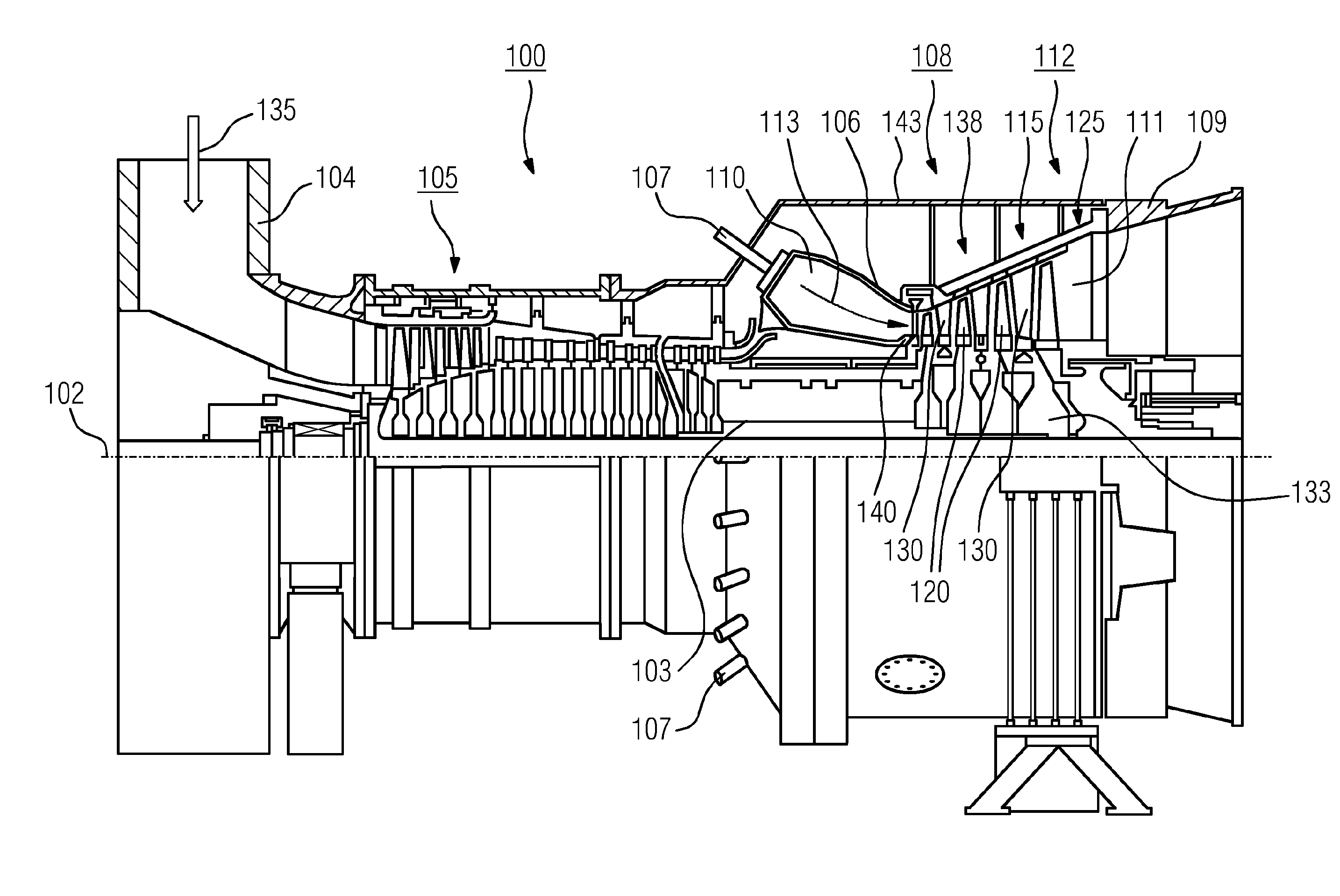
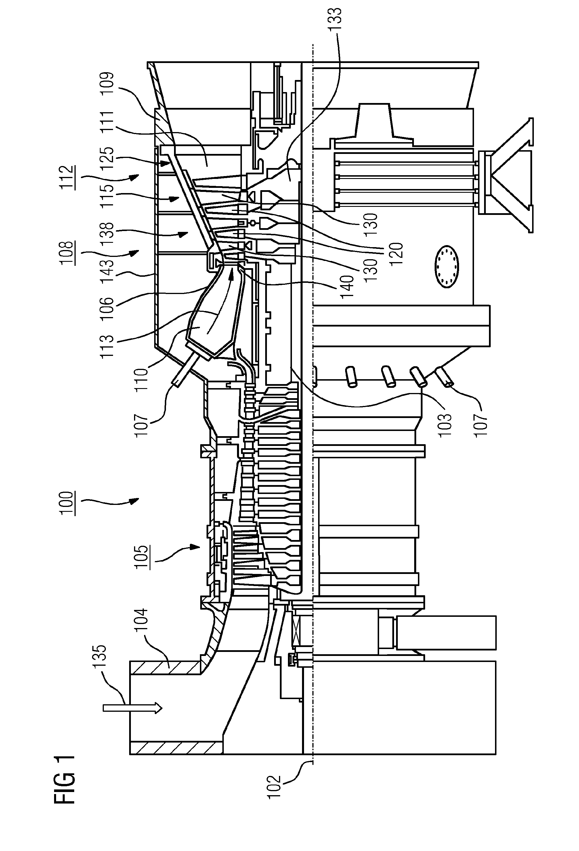
[0031]FIG. 1 shows a turbine 100, in this case a gas turbine, in partial longitudinal section. In the interior, the gas turbine 100 has a rotor 103 which is mounted such that it can rotate about an axis of rotation 102 (axial direction) and is also referred to as the turbine rotor. An intake housing 104, a compressor 105, a toroidal combustion chamber 110, in particular an annular combustion chamber 106, with a plurality of coaxially arranged burners 107, a turbine 108 and the exhaust-gas housing 109 follow one another along the rotor 103.

[0032]The annular combustion chamber 106 is in communication with an annular hot gas duct 111. There, for example, four series-connected turbine stages 112 form the turbine 108. Each turbine stage 112 is formed from two blade rings. As seen in the direction of flow of a working medium 113, in the hot gas duct 111 a row of stator blades 115 is followed by a row 125...


PUM


Abstract

A turbine blade has a pressure side, a suction side, and a cooling air channel, which is arranged between the pressure side and the suction side and which is bounded by inner surfaces of the pressure side and of the suction side. A cylindrical heat sink having a base surface, which has the shape of an aerofoil profile and has a profile top side and a profile bottom side, is arranged in the cooling air channel, which heat sink extends from the pressure side to the suction side. Turbulators are arranged on the inner surface of the pressure side and/or of the suction side in a region adjacent to the heat sink. The turbulators are arranged in such a way that lower air turbulence is produced in a region adjacent to the profile top side than in a region adjacent to the profile bottom side.

Description

CROSS REFERENCE TO RELATED APPLICATIONS[0001]This application is the US National Stage of International Application No. PCT / EP2014 / 064288 filed Jul. 4, 2014, and claims the benefit thereof. The International Application claims the benefit of European Application No. EP13178387 filed Jul. 29, 2013. All of the applications are incorporated by reference herein in their entirety.FIELD OF INVENTION[0002]The invention relates to a turbine blade having a pressure side, a suction side and, arranged therebetween, a cooling air duct bounded by inner surfaces of the pressure side and of the suction side, wherein in the cooling air duct there is arranged a cylindrical heat sink having a base surface in the shape of an airfoil profile, with a profile upper side and a profile underside, which extends from the pressure side to the suction side, wherein the base surface is in the inner surface of the pressure side or of the suction side, wherein turbulators are arranged on the inner surface of the ...

Claims


Application Information

Patent Timeline
Patent Type & Authority Applications(United States)
IPC IPC(8): F01D5/18
CPCF05D2260/2212F01D5/187Y02T50/60
Inventor AHMAD, FATHI
Owner SIEMENS AG
Why Eureka
Try Eureka