Turbine blade

Inactive Publication Date: 2016-06-02
SIEMENS AG
View PDF5 Cites 3 Cited by
  • Summary
  • Abstract
  • Description
  • Claims
  • Application Information

AI Technical Summary

Benefits of technology

[0021]The advantages achieved by the invention are in particular that a more uniform cooling is achieved, in particular at the profile tip of a turbine blade, by the specific diversion of the cooling air in a cooling air refresher into the direction of flow of the intended cooling duct. There is no crossing of the cooling air stream, as a result of which the number of co

Problems solved by technology

The invention is based here on the idea that the aerodynamic bypass between two cooling air ducts that is formed by the cooling air refreshers can sensitively disturb the cooling air stream, and consequently may lead to problems in the cooling of the turbine blade.
The stream consequently does not go over into the main direction, but impinges on the opposite wall almost unchecked, and is only limitedly available downstream of the cooling air refresher.
This is s

Method used


Image

  • Turbine blade
  • Turbine blade
  • Turbine blade

Examples


Embodiment Construction

[0028]The same parts are provided with the same designations in all of the figures.

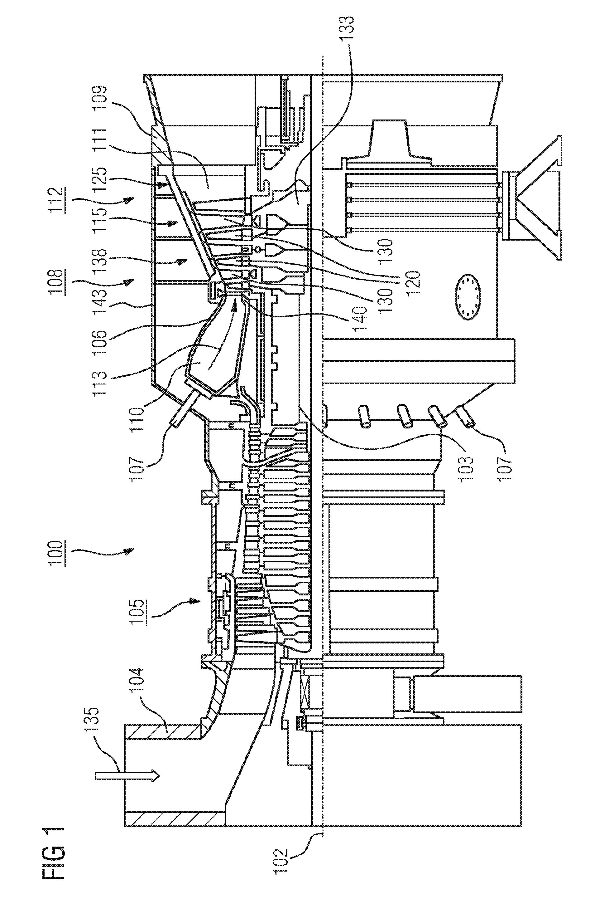
[0029]FIG. 1 shows a turbine 100, here a gas turbine, in a longitudinal partial section. The gas turbine 100 has inside a rotor 103, which is rotatably mounted about an axis of rotation 102 (axial direction) and is also referred to as a turbine rotor. Following one another along the rotor 103 are an intake housing 104, a compressor 105, a toroidal combustion chamber 110, in particular an annular combustion chamber 106, with a number of coaxially arranged burners 107, a turbine 108 and the exhaust housing 109.

[0030]The annular combustion chamber 106 communicates with an annular hot gas duct 111. There, for example four series-connected turbine stages 112 form the turbine 108. Each turbine stage 112 is formed from two blade rings. As seen in the direction of flow of a working medium 113, in the hot gas duct 111 a row of stationary blades 115 is followed by a row 125 formed from moving blades 120.

[0031]T...


PUM


Abstract

A turbine blade includes a first cooling air duct and a second cooling air duct which is separated from the first cooling air duct by a wall and which has a main direction, wherein the first and the second cooling-air duct are connected to one another by a first opening in the wall, wherein the wall has a second opening, to permit an improved cooling air action and thus higher operating temperatures and higher efficiency of the turbine. The second opening is adjoined by a diverting duct, the main direction of which, in the region in which the diverting duct issues into the second cooling air duct, is oriented substantially parallel to the main direction of the second cooling air duct.

Description

CROSS REFERENCE TO RELATED APPLICATIONS[0001]This application is the US National Stage of International Application No. PCT / EP2014 / 065205 filed Jul. 16, 2014, and claims the benefit thereof. The International Application claims the benefit of European Application No. EP13178390 filed Jul. 29, 2013. All of the applications are incorporated by reference herein in their entirety.FIELD OF INVENTION[0002]The invention relates to a turbine blade with a first cooling air duct and a second cooling air duct, which is separated from the first cooling air duct by a wall, is neighboring the first cooling air duct and has a main direction, wherein the first and second cooling air ducts are connected to one another at their respective end by a first opening in the wall, wherein the wall has a second opening, which separates the wall in a middle region into a first part and a second part.BACKGROUND OF INVENTION[0003]A turbine is a flow machine, which converts the internal energy (enthalpy) of a fl...

Claims


Application Information

Patent Timeline
IPC IPC(8): F01D5/18F01D5/02F01D25/12F01D5/14F01D9/04
CPCF01D5/187F01D5/147F01D9/041F01D25/12F05D2260/202F05D2220/32F05D2240/30F05D2240/12F01D5/02F01D5/18F01D5/188Y02T50/60
Inventor AHMAD, FATHIHESELHAUS, ANDREAS
Owner SIEMENS AG
Why Eureka
Try Eureka