Vehicular power source device

a power source device and battery technology, applied in the direction of battery/fuel cell propulsion, electrochemical generators, battery/fuel cell control arrangement, etc., can solve the problems of excessively high temperature shorten the life of the battery module, and reduce the performance of the entire plural battery module, so as to efficiently cool the cooled battery module. the effect of hard cooling

Inactive Publication Date: 2007-10-11
HONDA MOTOR CO LTD
View PDF2 Cites 38 Cited by
  • Summary
  • Abstract
  • Description
  • Claims
  • Application Information

AI Technical Summary

Benefits of technology

[0024] With the above arrangement, since the position of the coolant supply port is displaced to the side opposite from the displacement direction with respect to the center in the longitudinal dire

Problems solved by technology

Since the plurality of battery modules are electrically connected in series, if any of them is not sufficiently cooled and its temperature is raised, the life of the battery module is shortened, and further there is a problem that performance of the entire plural battery modules is lowered.
Particularly, if the number of battery modules constituting each layer is different from each other, cooling tends to be insufficient for the batter

Method used


Image

  • Vehicular power source device
  • Vehicular power source device
  • Vehicular power source device

Examples


first embodiment

[0036] the present invention will be described based on FIGS. 1 to 7.

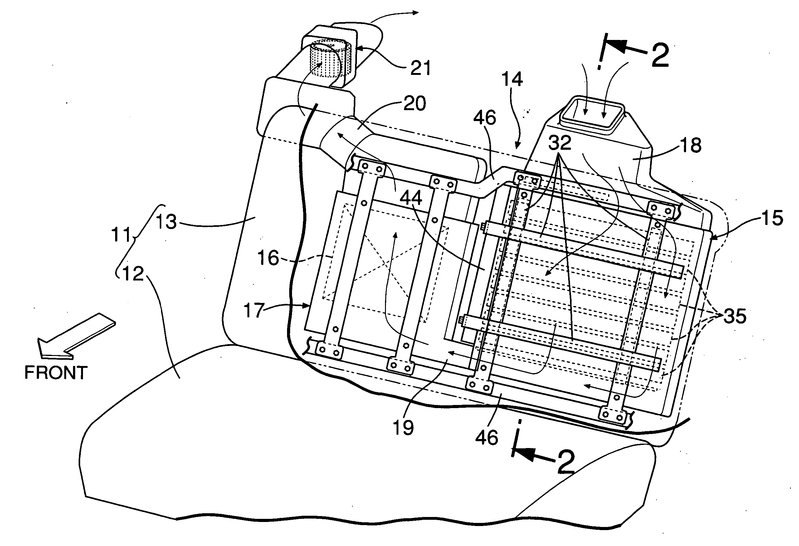
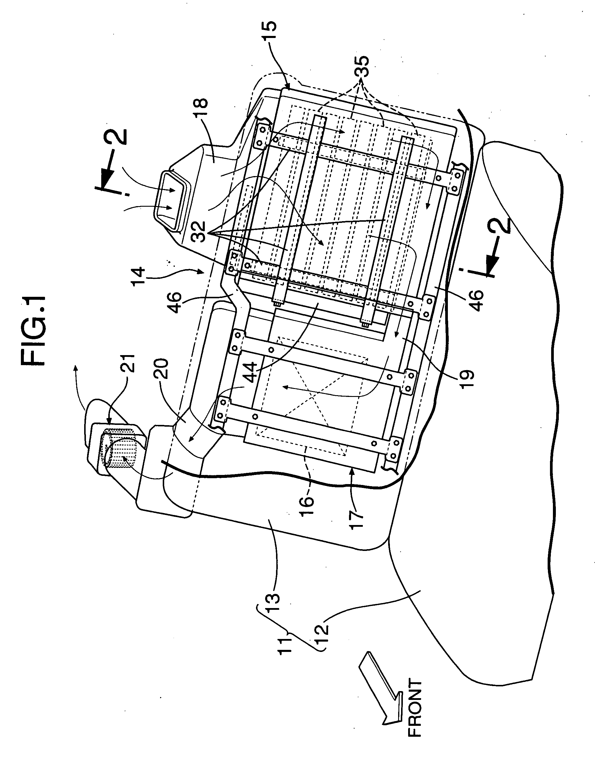
[0037] As shown in FIG. 1, a power source device 14 is disposed on the rear face of a seat back 13, rising diagonally rearward from the rear end of a seat cushion 12 of a rear seat 11 in a hybrid vehicle having an engine and a motor generator, and is connected to THE motor generator, as a power source for driving. The power source device 14 comprises: a battery box 15 for storing a battery; an electric equipment box 17 for storing electric equipment 16, such as an inverter; a cooling-air supply duct 18 for introducing cooling air as a coolant to the battery box 15; an intermediate duct 19 for guiding the cooling air from the battery box 15 to the electric equipment box 17; a cooling-air discharge duct 20 for discharging the cooling air from the electric equipment box 17; and an electric fan 21 (a negative air pressure source) provided at the downstream end of the cooling-air discharge duct 20.

[0038] Next, the stru...

second embodiment

[0058] The power source device 14 in the second embodiment is stored in a recess 62a formed in a floor panel 62 of a trunk room 61 of an automobile. The recess 62a is a place generally used for storing a spare tire. Using this place for storing the power source device 14 enables an effective use of space.

[0059] The battery modules 35 are arranged vertically in three layers. The lower first layer comprises 9 battery modules 35, the central second layer comprises 10 battery modules 35, and the upper third layer comprises 11 battery modules 35.

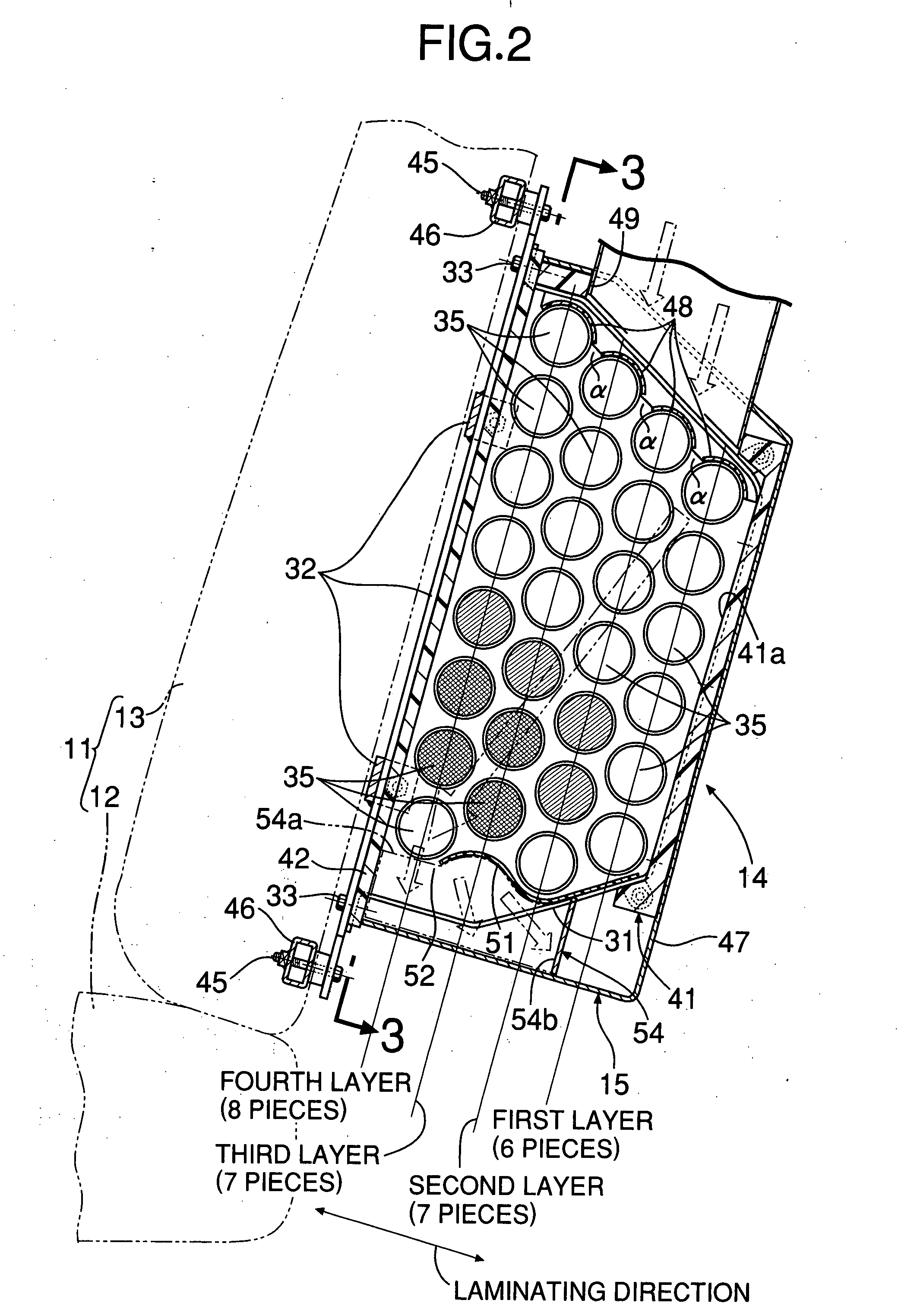
[0060] The cooling-air supply duct 18 uniformly supplies the cooling air to the first to the third layers through the cooling-air supply port 49 formed in the battery case 41 of the battery box 15 and three pieces of the first air-introduction guides 48. The second air-introduction guide 51 is inclined diagonally upward on the downstream side of the cooling-air flow direction, and the bottom wall 41a of the battery case 41 is inclined so that th...


PUM


Abstract

A vehicle power source includes a number of battery modules in a first layer on one end side in a battery module laminating direction which is smaller than the number of battery modules in a fourth layer on an other end side. A cooling-air supply port is opened over the entire region in the laminating direction of the battery modules, an air-introduction guide is provided on the downstream side in the cooling-air flow direction, and a coolant discharge port is opened at a position closer to the fourth layer side. A flow from the first layer side to the fourth layer side is formed on the downstream side in the cooling-air flow direction so as to efficiently cool the battery modules difficult to be cooled.

Description

RELATED APPLICATION DATA [0001] The Japanese priority application Nos. 2006-104152 and 2006-104153 upon which the present application is based are hereby incorporated, in their entirety, by reference. BACKGROUND OF THE INVENTION [0002] 1. Field of the Invention [0003] The present invention relates to a vehicular power source device comprising: a battery box including a coolant supply port and a coolant discharge port; cylindrical battery modules juxtaposed in a plurality of laminated planes, in which a coolant flows in a direction orthogonal to a longitudinal direction of the battery modules, from the coolant supply port to the coolant discharge port, so as to cool the battery modules. [0004] Also, the present invention relates to a vehicular power source device comprising: a battery box including a coolant supply port and a coolant discharge port; and a plurality of battery modules arranged in parallel are stored in the battery box, in which a coolant flows in a direction orthogona...

Claims


Application Information

Patent Timeline
IPC IPC(8): H01M10/50
CPCH01M10/4207H01M10/5004H01M10/5008H01M10/5073H01M10/503H01M10/5067H01M10/5016B60L2240/545B60L50/64B60L58/26H01M10/613H01M10/617H01M10/625H01M10/643H01M10/6563H01M10/6566Y02E60/10Y02T10/70
Inventor KUBOTA, SHINYASAKAI, HIDEAKITAKEDOMI, HARUMIOYA, SATOYOSHI
Owner HONDA MOTOR CO LTD
Why Eureka
Try Eureka