Battery pack and electrically powered vehicle including the battery pack

Active Publication Date: 2012-04-05
GS YUASA INT LTD
View PDF9 Cites 39 Cited by
  • Summary
  • Abstract
  • Description
  • Claims
  • Application Information

AI Technical Summary

Benefits of technology

[0012]An object of the present invention is to provide a battery pack that can uniformly cool a plurality of electric cells, prevent a breakdown of t

Problems solved by technology

However, the electric cell (secondary cell) tends to generate heat due to charge and discharge, and an excessive temperature rise of the electric cell causes a reduction in performance of the electric cell and a shortened life span.
However, the gas is supplied to the first passage from a predetermined location of the first passage in the battery pack, and therefore the electric cells in a downstream area of the first passage may not be sufficiently cooled.
More specif

Method used


Image

  • Battery pack and electrically powered vehicle including the battery pack
  • Battery pack and electrically powered vehicle including the battery pack
  • Battery pack and electrically powered vehicle including the battery pack

Examples


Example

[0064]An embodiment of the present invention will now be described with reference to the attached drawings.

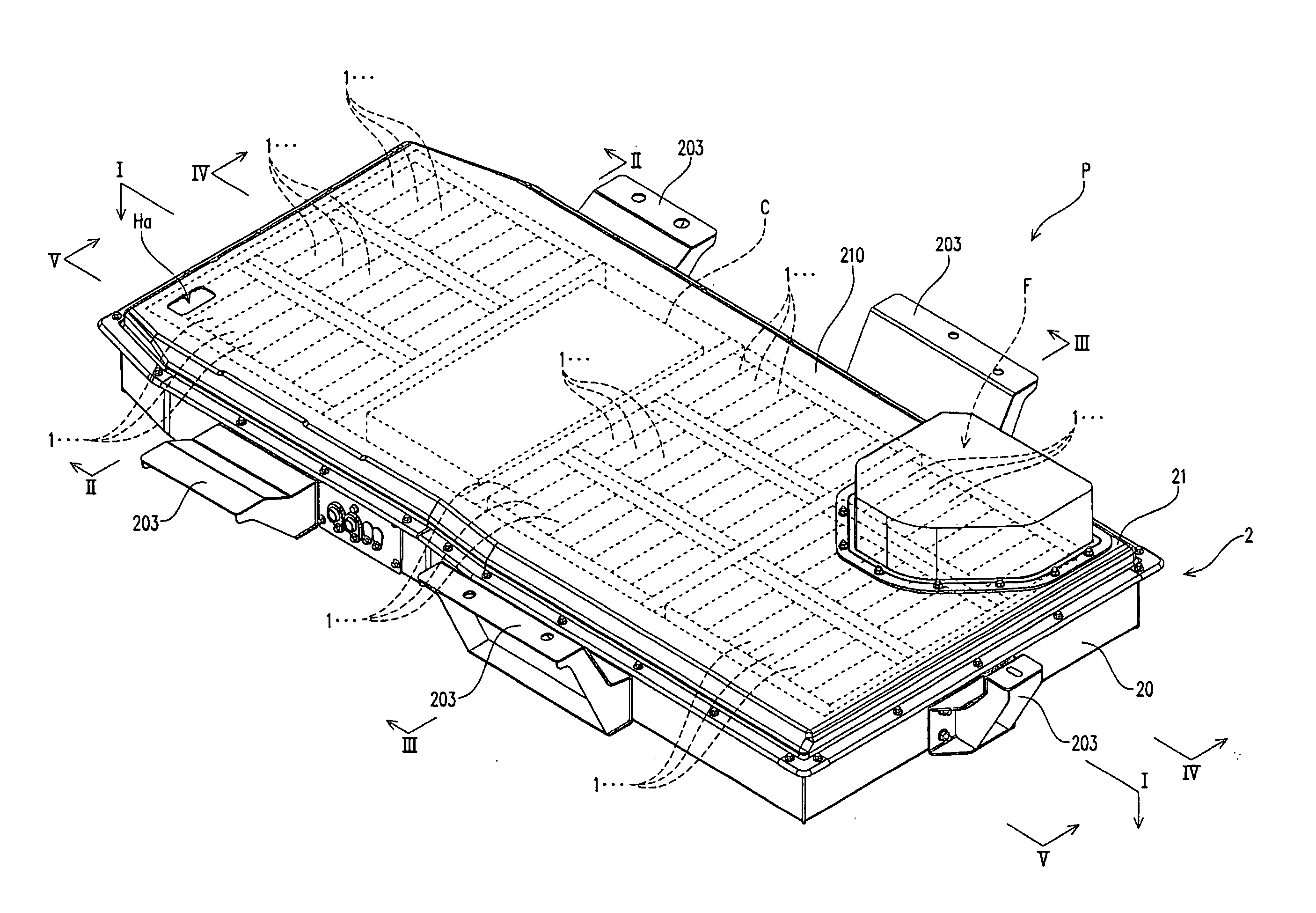
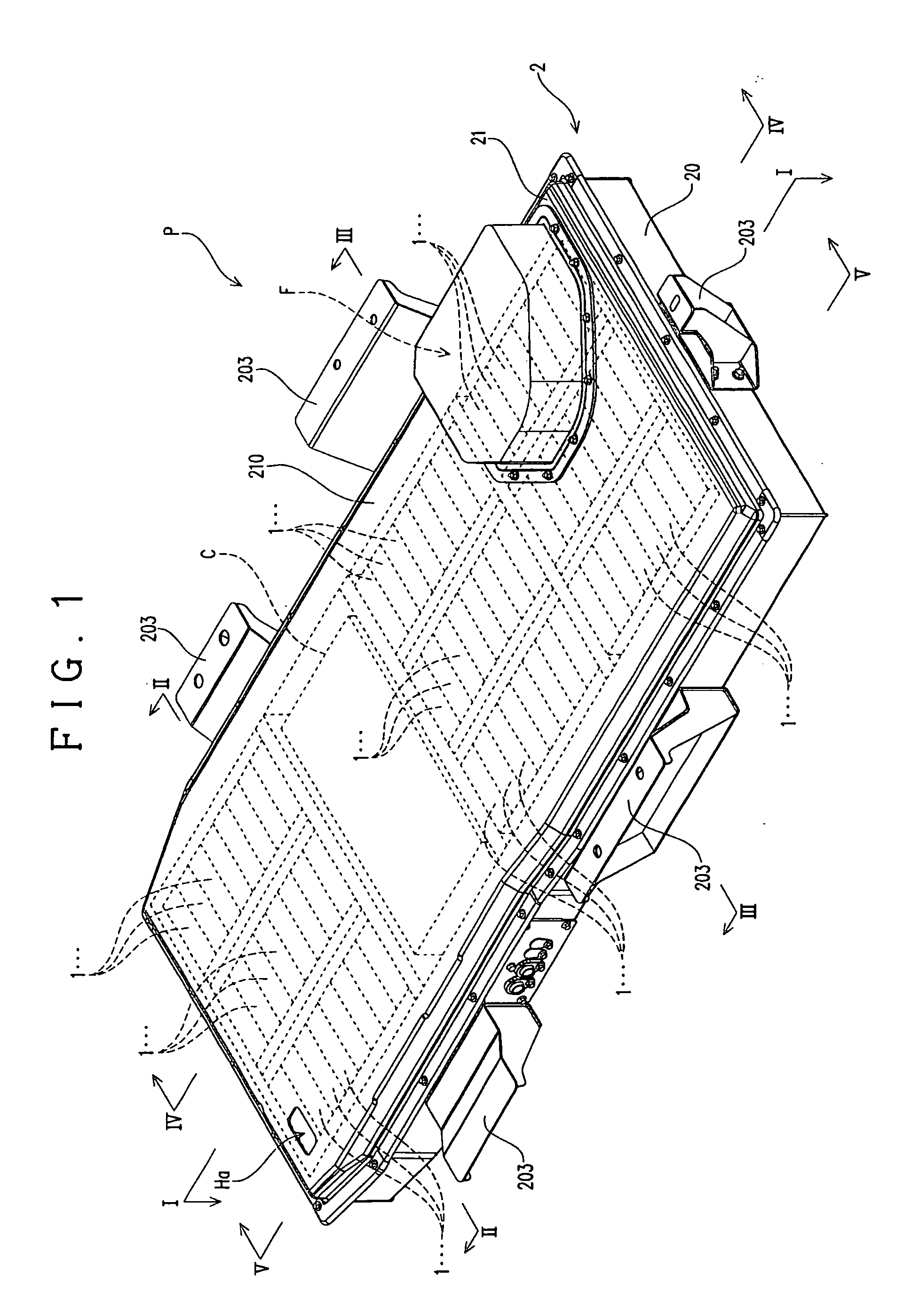
[0065]A battery pack according to the present embodiment is adopted as a power source of an electrically powered vehicle, such as an electric vehicle (EV) and a hybrid electric vehicle (HEV). As shown in FIG. 1, the battery pack includes a plurality of electric cells 1 and a packaging case 2 that accommodates the plurality of electric cells 1.

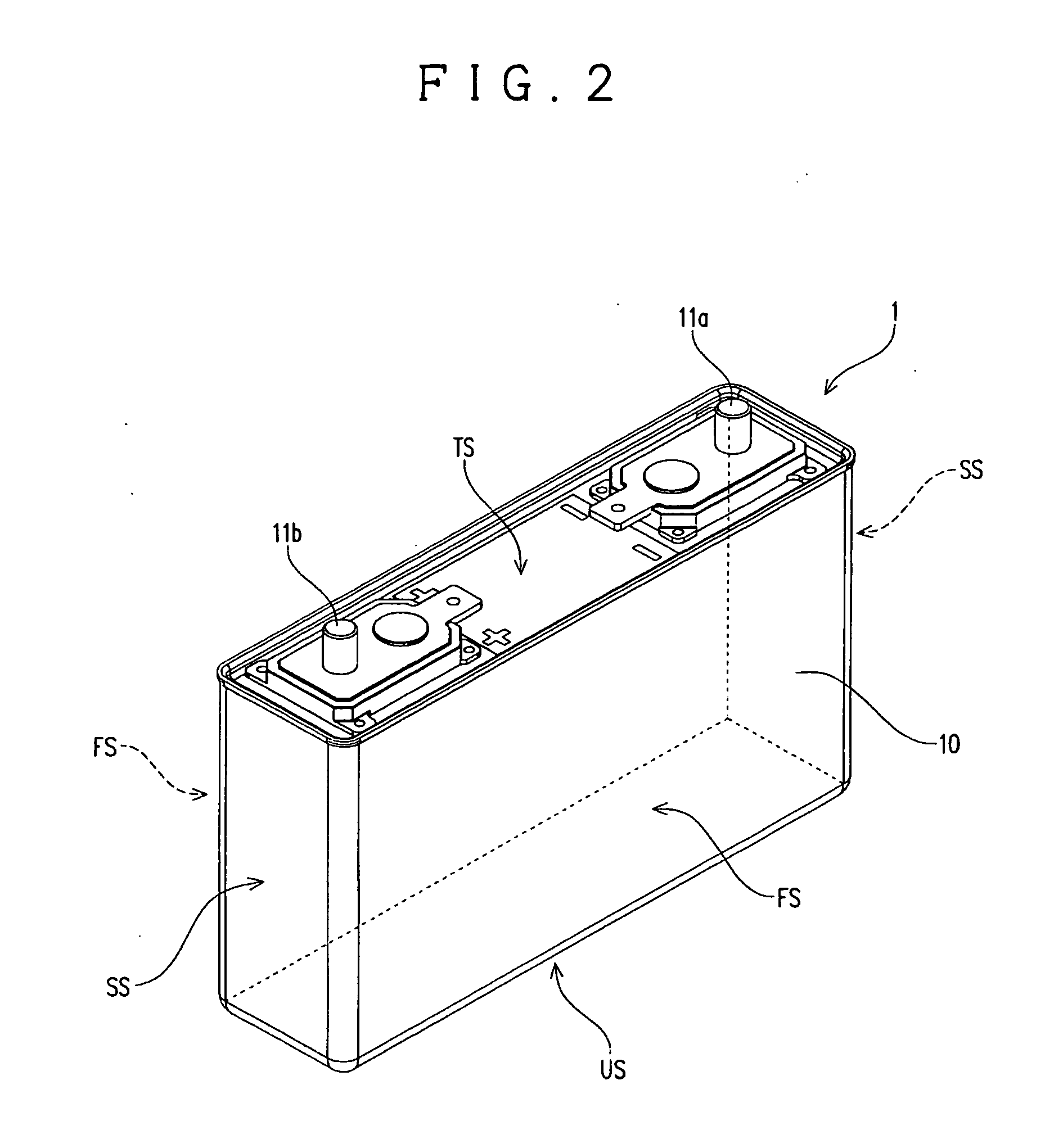
[0066]As shown in FIG. 2, the electric cell 1 includes an electrode element (not shown), a cell case 10 that accommodates the electrode element, and connection terminals 11a and 11b for external connection arranged on an outer surface of the cell case 10. The connection terminals 11a and 11b are electrically connected to the electrode element.

[0067]The electric cell 1 is a so-called rectangular cell in which the cell case 10 is formed in a six-sided shape. The positive electrode connection terminal 11a and the negative electrode connection...


PUM


Abstract

Provided is a battery pack that can uniformly cool a plurality of electric cells, prevent a breakdown of the electric cells, and provide high performance of all electric cells. The battery pack includes a packaging case in which: each adjacent ones of a plurality of electric cells in the first direction define a ventilation space; first and second passages are defined that extend in the first direction and that are arranged to have the plurality of electric cells located between the first and second passages in a second direction intersecting the first direction, wherein gas supplied to the first passage flows through the ventilation spaces to the second passage; and a flow rate limitation device is provided that is arranged in an upstream area of the first passage and that limits a flow rate of the gas flowing through one of the plurality of ventilation spaces, which leads to the upstream area of the first passage, to a predetermined flow rate.

Description

CROSS REFERENCE TO RELATED APPLICATION[0001]This application claims priority from Japanese Patent Application No. 2010-222656, which is incorporated herein by reference.TECHNICAL FIELD[0002]The present invention relates to a battery pack adopted as a power source of various devices. More specifically, the present invention relates to a battery pack including a high-capacity assembled battery constituted by a plurality of electric cells and to an electrically powered vehicle including the battery pack.BACKGROUND ART[0003]Conventionally, there are various types of power sources for various devices that require a large amount of power. A battery pack that includes a plurality of electric cells and a packaging case accommodating the plurality of electric cells is known as an example of the power sources.[0004]In recent years, hybrid electric vehicles that emit less CO2 and electric vehicles that do not emit CO2 (hereinafter, the vehicles will be collectively referred to as “electrically...

Claims


Application Information

Patent Timeline
IPC IPC(8): H01M2/12H01M10/00H01M2/10H01M2/02H01M50/77H01M10/60H01M10/613H01M10/625H01M10/647H01M10/651H01M10/6553H01M10/6563H01M10/6566H01M50/209H01M50/271
CPCH01M2/1077H01M10/5004H01M10/5073H01M10/5032H01M10/5067H01M10/5016H01M10/625H01M10/6563H01M10/647H01M10/6566H01M10/613Y02E60/10H01M50/209H01M50/271
Inventor WATANABE, MINORUKAWAHARA, SHINGO
Owner GS YUASA INT LTD
Why Eureka
Try Eureka