Gas distribution garment

Inactive Publication Date: 2006-02-09
WL GORE & ASSOC INC
View PDF29 Cites 38 Cited by
  • Summary
  • Abstract
  • Description
  • Claims
  • Application Information

AI Technical Summary

Benefits of technology

[0007] The present invention is directed to a gas distribution garment system which can be used with sealed garments such as are used in hazardous or toxic environments, as well as in other applications where the subject is exposed to high heat stress situations such as fire-fighters, clean room operatives or hospital theatre operatives. In a preferred embodiment, a gas distribut

Problems solved by technology

It is well known that subjecting a person to prolonged periods of inadequate heat dissipation leads to an increase in body temperature (heat stress), indicated by undesirable effects such as discomfort, increased fatigue, decreased physical and intellectual performance and, in extreme cases, death.
Body core temperatures in excess of 38° C. will, for example, lead to impaired decision making and increased reaction times whereas core temperatures in excess of 40° C. can cause physiological damage and fatalities.
Personnel such as fire-crews, “hazmat” operatives such as those working on toxic or generally hazardous cleanup operations, and chemical plant operatives handling hazardous products are potential victims of such heat stress.
Such personnel have usually to wear virtually totally sealed garments which severely inhibit cooling effects that would naturally occur due to ambient air flow over the persons skin and clothing.
Given the multi-layer construction of the garment and the inclusion of the corrugated spacer layer the flexibili

Method used


Image

  • Gas distribution garment
  • Gas distribution garment
  • Gas distribution garment

Examples


example 1

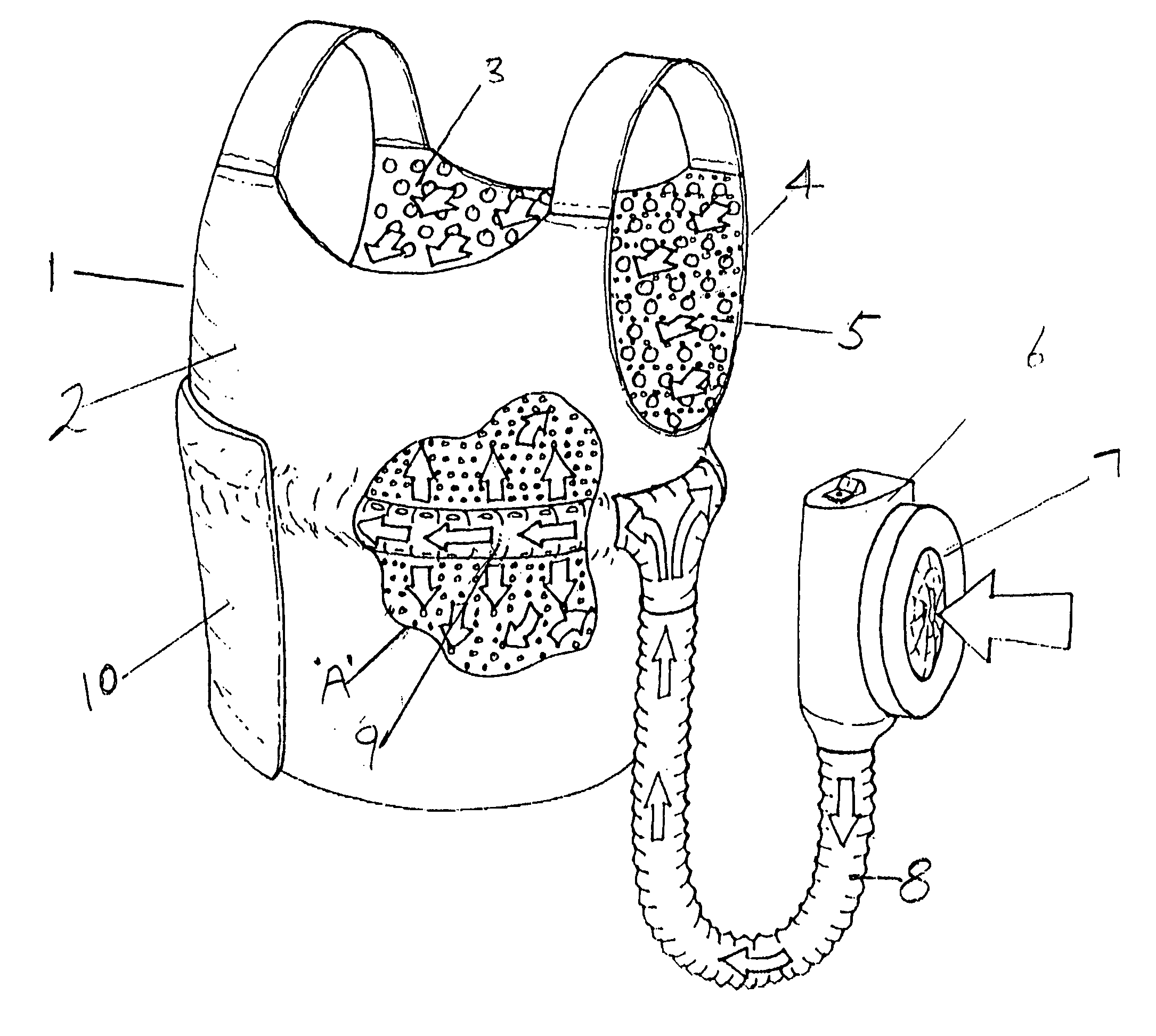
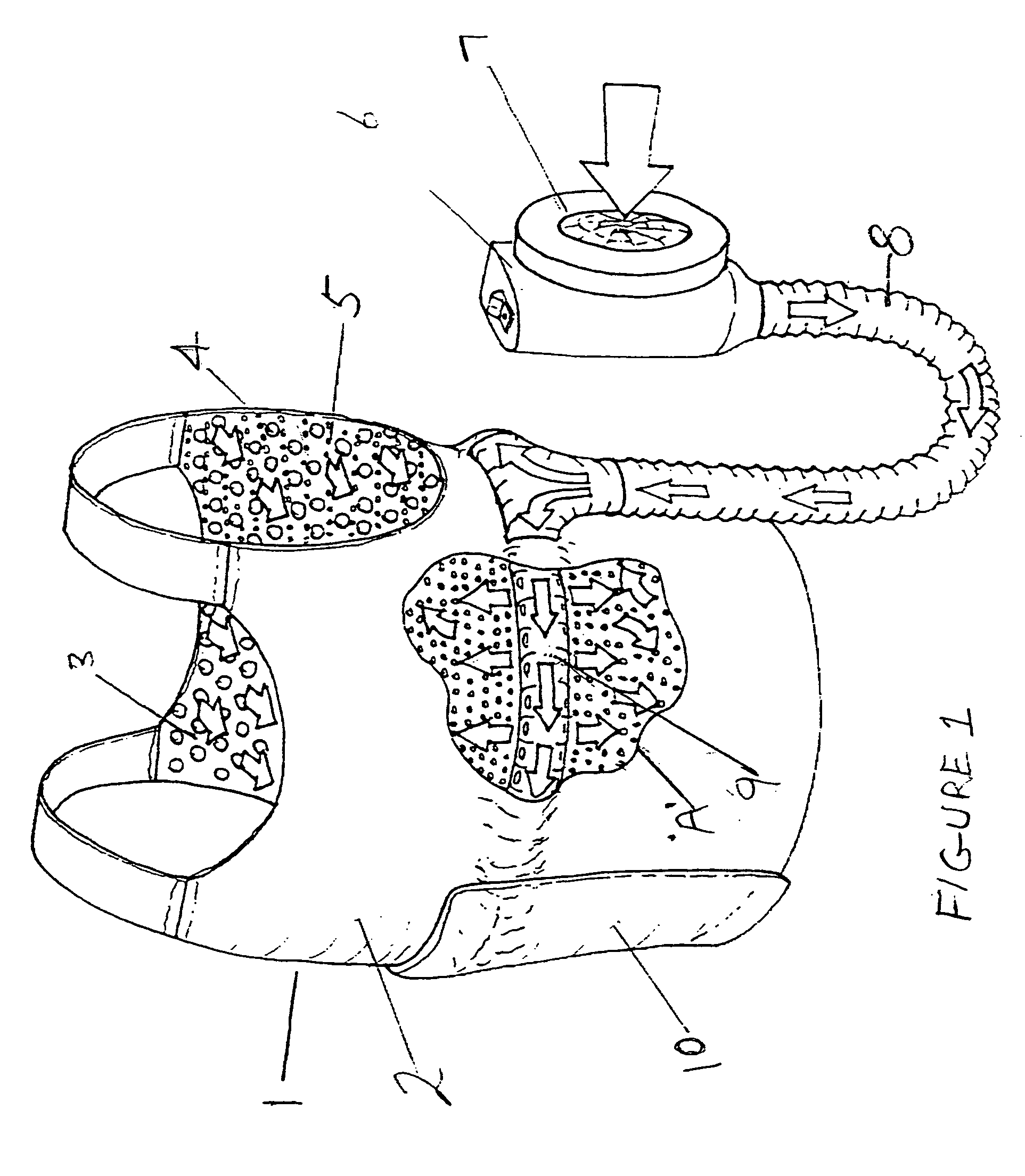
[0046] To demonstrate the efficacy of an embodiment of the invention a garment was constructed according to the teaching of this specification and its cooling effectiveness evaluated whilst being worn by a human subject walking on a tread-mill.

[0047] The first and second substrates comprised a laminate of Basofil® spun bonded non-woven textile and expanded polytetrafluoroethylene having an air-impermeable water vapour permeable coating with a plurality of foamed silicone rubber protrusions uniformly distributed on the Basofil® surface. The laminate is available from W.L.Gore and Associates GmbH, Putzbrunn, Germany under the trade name Airlock® Part No. AIRL 002000. The silicone rubber protrusions are approximately 3 mm in height and cover an area of approximately 13% of the surface of the laminate.

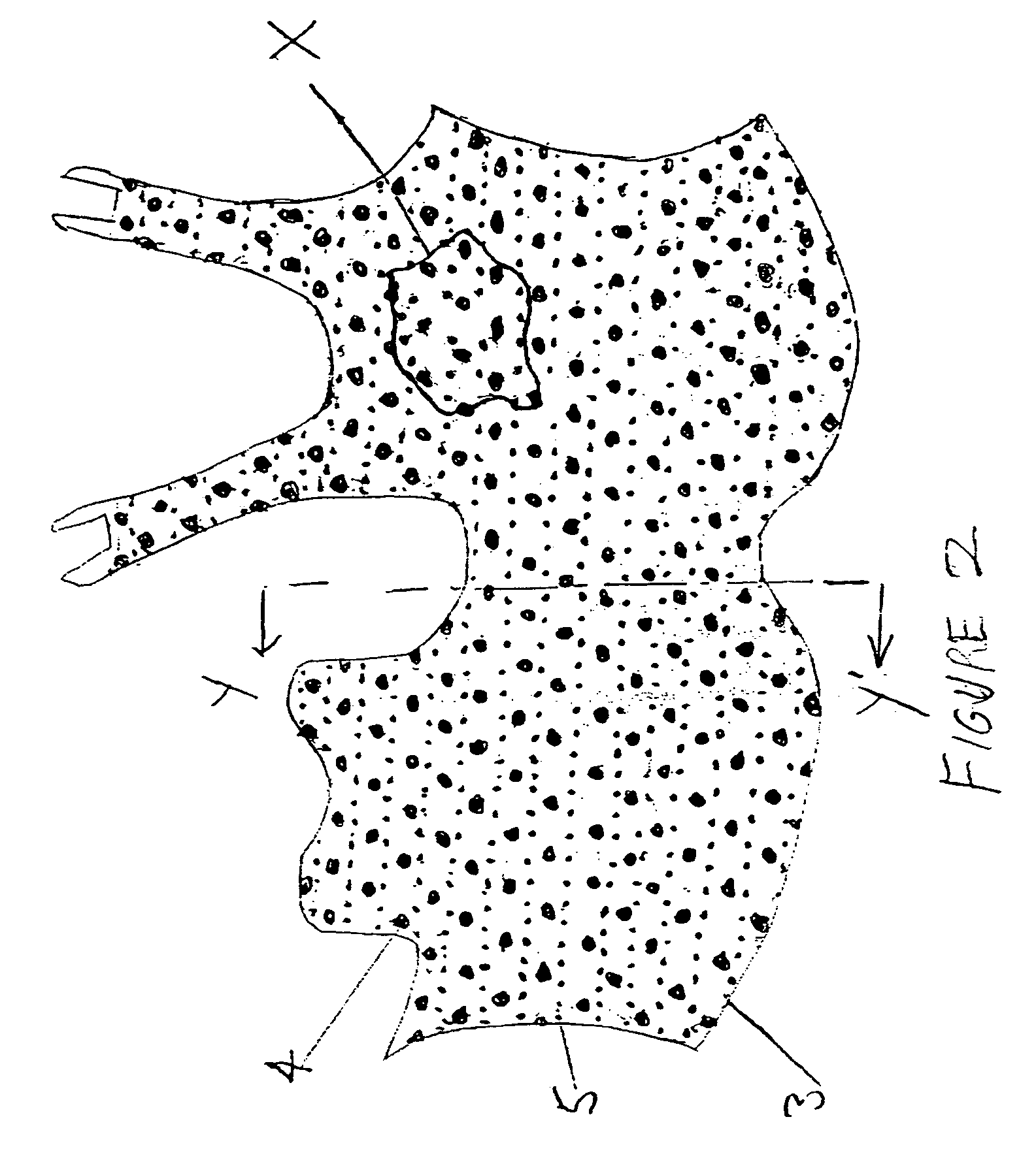
[0048] Two pieces of Airlock® AIRL 002000 laminate were cut and sized according to FIG. 2 to give a body coverage of about 0.45 m2. The laminate corresponding to the second substrate of ...

example 2

Cooling

[0061] To evaluate the cooling power of the cooling garment prepared substantially according to Example 1, it was subject to Thermally Instrumented Manikin testing by The Cord Group Ltd., Dartmouth, Nova Scotia, Canada. The cooling garment was tested in combination with a standard British Army Mk IV protective suit as used in the foregoing Example 1 and under the various conditions as detailed in the following Table 1. Testing was carried out in a temperature and humidity controlled room with an ambient temperature set at 35° C. and relative humidity set 50%. Details of the test methodology are as follows.

Test Method

[0062] The evaluation of cooling vest prototypes using UK standard suit ensemble was conducted using a Thermal Instrumented Manikin Test System. During the testing, environment temperature, skin temperature and power consumption were recorded.

[0063] The Thermal Manikin Test System consists of a hollow aluminum manikin equipped with temperature sensors and el...


PUM


Abstract

A garment for cooling the body of a wearer is described which comprises a substantially gas impermeable first substrate and a gas-permeable second substrate attached to form a cavity. At least one of the first and second substrates comprising a plurality of raised protrusions on a surface within the cavity, and the gas permeable second substrate comprising a plurality of raised protrusions on the surface external to the cavity and proximate to the body of the wearer. The cavity is adapted to be connected to a gas supply such that the gas flows into the cavity and exits the cavity through the gas permeable second substrate. The cooling garment is light weight and conformable, and may be non-tethered for portability.

Description

FIELD OF THE INVENTION [0001] The present invention relates to a personal gas distribution garment, preferably a ventilated cooling garment. One embodiment is directed to a ventilated cooling garment for use by a wearer who is clad in a sealed overall suit and breathing system which is designed to protect the wearer from harmful chemical, biological or other environmental hazards. It is also a function of the ventilated cooling garment of the present invention that it may be adapted to use filtered ambient air as the ventilating cooling medium. Further desirable attributes of the garment are high cooling power, low weight, low bulk, good flexibility, and high water vapour permeability, all of which contribute to the comfort of the wearer. BACKGROUND OF THE INVENTION [0002] It is well known that subjecting a person to prolonged periods of inadequate heat dissipation leads to an increase in body temperature (heat stress), indicated by undesirable effects such as discomfort, increased ...

Claims


Application Information

Patent Timeline
IPC IPC(8): A41D13/015
CPCA61F2007/0063A41D13/0053A41D31/145A41D27/28
Inventor FARNWORTH, BRIANDACEY, PAUL
Owner WL GORE & ASSOC INC
Why Eureka
Try Eureka