
Electric insulation cold conduction structure

Pending Publication Date: 2021-11-23
上海电气(集团)总公司智惠医疗装备分公司
View PDF0 Cites 0 Cited by
  • Summary
  • Abstract
  • Description
  • Claims
  • Application Information

AI Technical Summary

Problems solved by technology

However, most of the electrical insulation and cold conduction structures in the prior art are very complicated, the cost is high, and the electrical insulation is prone to failure

Method used


Image

  • Electric insulation cold conduction structure
  • Electric insulation cold conduction structure
  • Electric insulation cold conduction structure

Examples


Embodiment Construction

[0041] The implementation of the present invention will be illustrated by specific specific examples below, and those skilled in the art can easily understand other advantages and effects of the present invention from the contents disclosed in this specification.

[0042] It should be noted that the structures, proportions, sizes, etc. drawn in the drawings of this specification are only used to match the content disclosed in the specification, for those who are familiar with this technology to understand and read, and are not used to limit the conditions for the implementation of the present invention. Therefore, there is no technical substantive meaning, and any modification of structure, change of proportional relationship or adjustment of size shall still fall within the scope of the disclosure of the present invention without affecting the functions and objectives of the present invention. within the scope of technical content. At the same time, terms such as "upper", "lo...


PUM

PropertyMeasurementUnit
Thicknessaaaaaaaaaa
Thicknessaaaaaaaaaa

Abstract

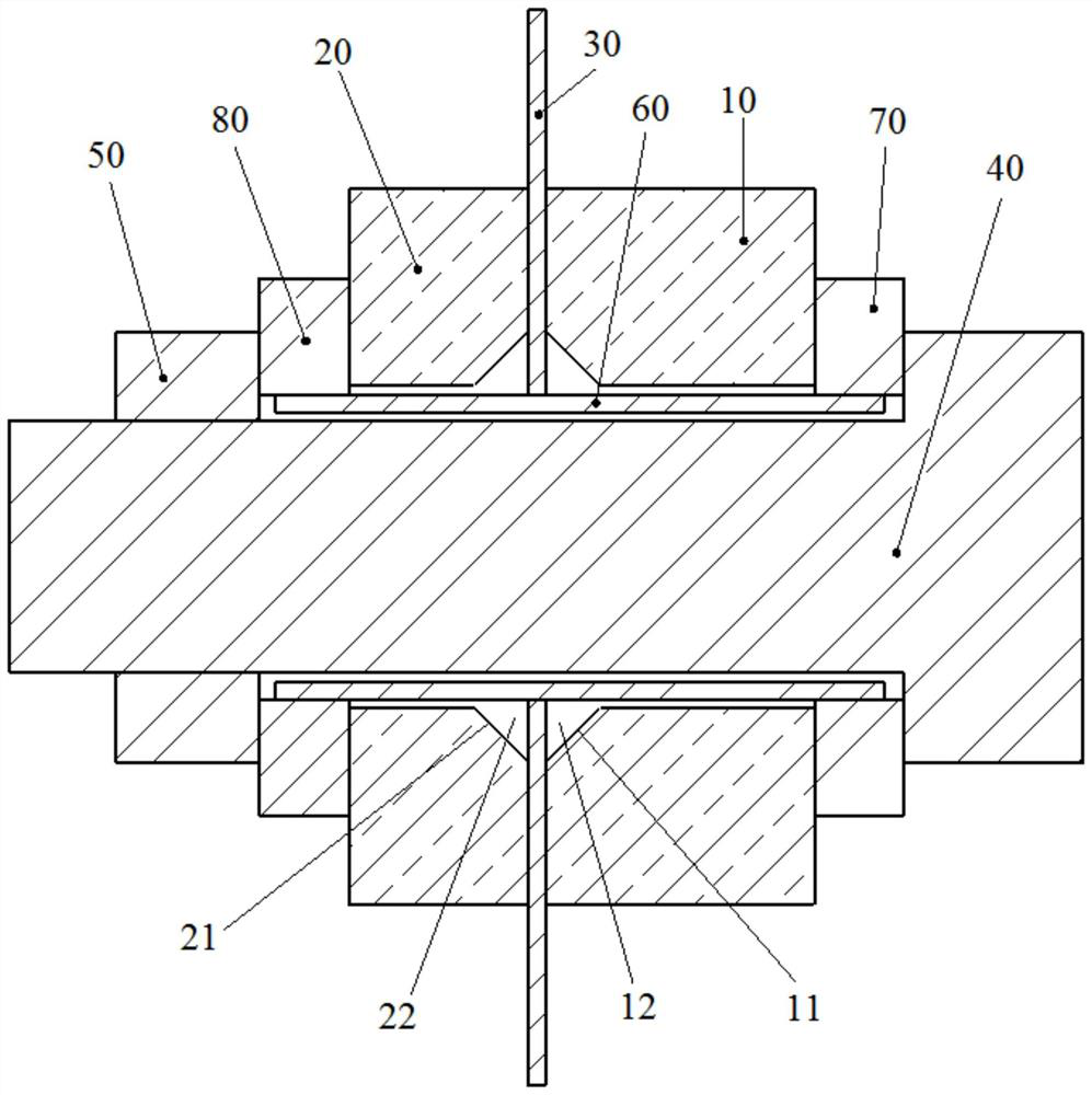
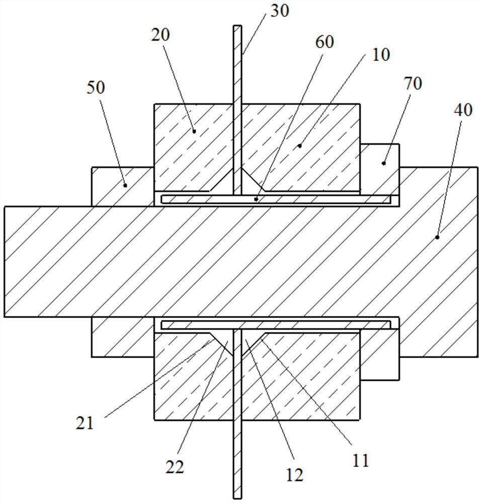
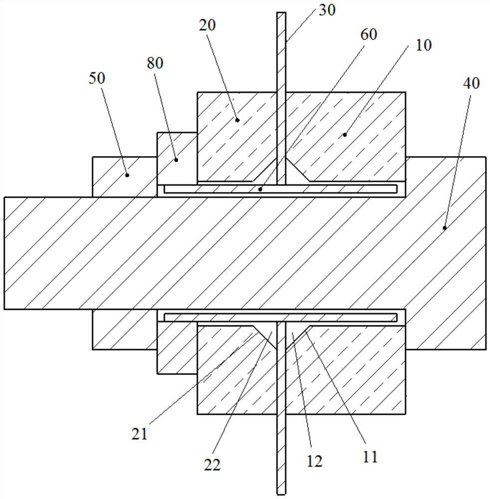
The invention provides an electric insulation cold conduction structure which comprises a first metal piece, a second metal piece, a pre-tightening assembly, an insulation assembly and an insulation cold conduction sheet distributed between the first metal piece and the second metal piece, and at least one of the first metal piece and the second metal piece is electrified. One of the first metal piece and the second metal piece is used for being connected with a refrigerating machine. The pre-tightening assembly enables the first metal piece, the insulation cold conduction sheet and the second metal piece to be tightly pressed. The insulation assembly enables the first metal piece and the second metal piece to be insulated. One of the first metal piece and the second metal piece, which is connected with the refrigerator, cools the other metal piece through the very thin insulating cold conduction sheet, so that cold conduction is realized, and insulation is achieved through the insulation cold conduction sheet and the insulation assembly. Thus, good cold conduction efficiency is guaranteed, the cold conduction path and the conductive path are not subjected to electric leakage, and finally good insulation between the first metal piece and the second metal piece and temperature difference as small as possible are guaranteed.

Description

technical field [0001] The invention relates to the technical field of application of superconducting magnets, in particular to an electrically insulating and cold-conducting structure. Background technique [0002] Magnetic resonance imaging (MRI) uses the magnetic resonance phenomenon of atomic nuclei (such as protons) under a highly uniform magnetic field to image different tissues and organs in the human body, thereby realizing medical diagnosis and other functions. At the end of 1978, the first magnetic resonance system was born in a log cabin at the Siemens research base in Erlangen, Germany. In late 1979, when the system finally worked, its first work was an image of a chili pepper. In March 1980, the first human brain image was obtained, and the data collection time at that time was 8 minutes. In 1983, Siemens successfully installed the first clinical magnetic resonance imaging equipment at the Hannover Medical School in Germany. The magnetic field strength of this...

Claims


Application Information

Patent Timeline
IPC IPC(8): H01F6/04
CPCH01F6/04
Inventor 宋天峰张涛邱胜顺陈荣王燕燕周振捷晏金炜
Owner 上海电气(集团)总公司智惠医疗装备分公司
Learn More