
Battery box heat dissipation system and heat dissipation method thereof

A heat dissipation system and battery box technology, which is applied to batteries, secondary batteries, circuits, etc., can solve the problems of battery pack stability decline, large temperature rise, and heat dissipation device damage, and achieve the best heat dissipation effect

Inactive Publication Date: 2018-03-30
SHENZHEN ANDING NEW ENERGY TECH DEV CO LTD
View PDF0 Cites 0 Cited by
  • Summary
  • Abstract
  • Description
  • Claims
  • Application Information

AI Technical Summary

Problems solved by technology

At present, the battery box is designed as a closed environment. The heat generated by the battery during charging and discharging, and the accumulation of hot and cold expansion air pressure will cause excessive temperature rise, and multiple sets of heat dissipation devices (fans, etc.) inside are turned on for a long time. The damage or failure of a single internal cooling device is unknown, and the local temperatures of multiple groups of multiple internal cooling devices cannot be coordinated, which greatly reduces the stability of the battery pack.
The existing cooling device consumes a lot of power when it works at full load all year round, which greatly reduces the service life of the cooling device

Method used


Image

  • Battery box heat dissipation system and heat dissipation method thereof
  • Battery box heat dissipation system and heat dissipation method thereof
  • Battery box heat dissipation system and heat dissipation method thereof

Examples


Embodiment Construction

[0024] In order to make the object, technical solution and beneficial technical effects of the present invention clearer, the present invention will be further described in detail below in conjunction with the accompanying drawings and specific embodiments. It should be understood that the specific implementations described in this specification are only for explaining the present invention, not for limiting the present invention.

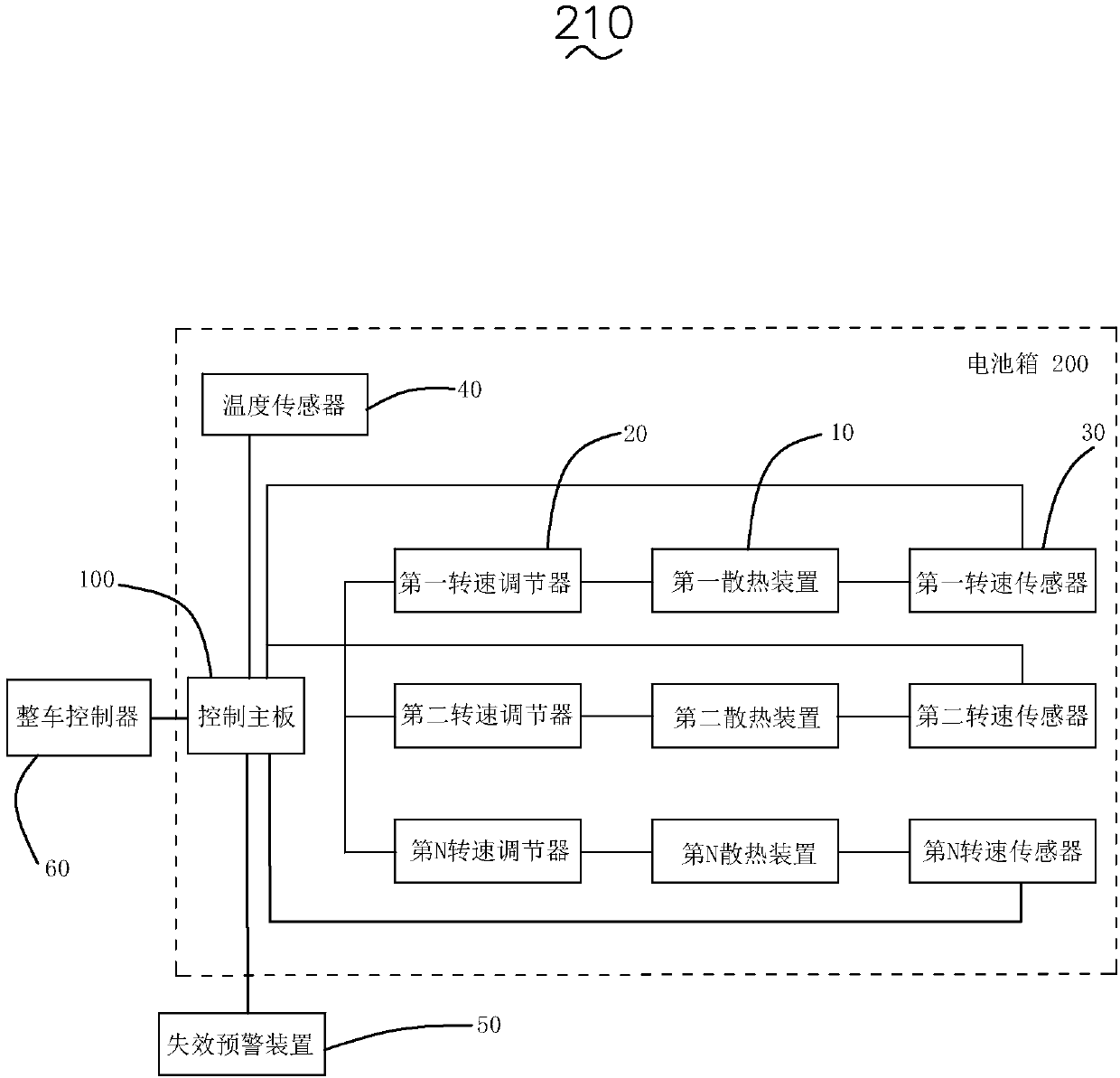
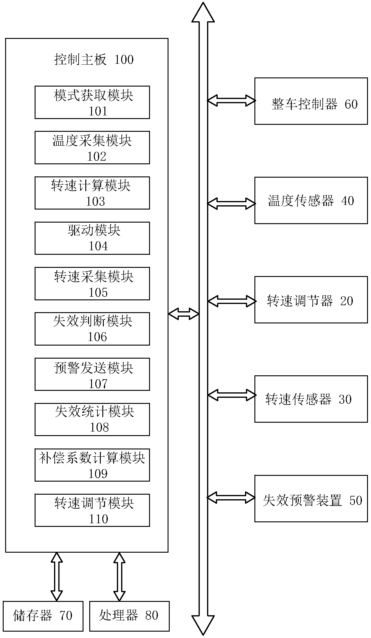
[0025] see figure 1 , the present invention provides a battery box cooling system 210, including a battery box 200, a control board 100, a plurality of cooling devices 10, a plurality of speed regulators 20, a plurality of speed sensors 30, a temperature sensor 40 and a The failure warning device 50 outside 200.

[0026] A plurality of cooling devices 10 , a plurality of rotation speed regulators 20 , a plurality of rotation speed sensors 30 and the temperature sensor 40 are all disposed in the battery box 200 . In this embodiment, the heat dissi...


PUM


Abstract

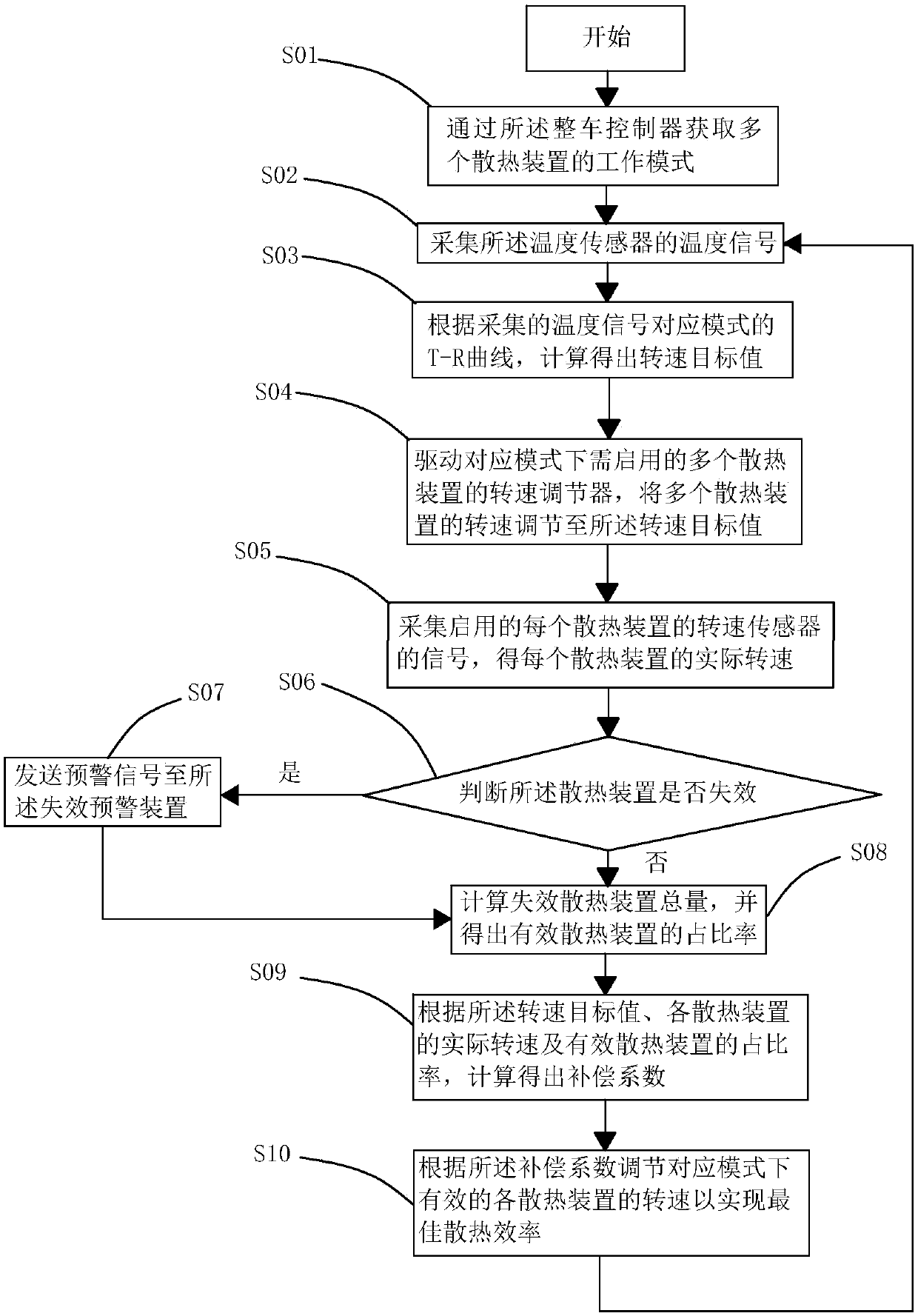
The invention relates to a battery box heat dissipation system and a heat dissipation method thereof. The system consists of a battery box, a control main board, a plurality of heat dissipating devices, a plurality of rotation speed regulators, a plurality of rotation speed sensors, a temperature sensor, and a failure early warning device disposed outside the battery box. Each heat dissipating device is equipped with a corresponding rotation speed regulator to regulate the rotation speed, and each rotation speed regulator is in connection with the control main board. Each heat dissipating device is equipped with a rotation speed sensor for acquiring the rotation speed of the corresponding heat dissipating device. Each rotation speed sensor is connected to the control main board. The temperature sensor is connected to the control main board. The failure early warning device is in communication connection with the control main board. The control main board is connected to a vehicle control unit. The battery box heat dissipation system and the heat dissipation method provided by the invention can automatically adjust the rotation speed of the heat dissipating devices, calculate the compensation coefficient to adjust the balance, and coordinate the heat dissipating devices to achieve optimal heat dissipation efficiency.

Description

【Technical field】 [0001] The invention relates to the technical field of battery box heat dissipation, in particular to a battery box heat dissipation system and a heat dissipation method thereof. 【Background technique】 [0002] At present, the electric vehicle industry is developing rapidly, and people's demand for electric vehicles is also increasing. With the popularity of power batteries, fast charging has become a goal that people are constantly pursuing. At present, the battery box is designed as a closed environment. The heat generated by the battery during charging and discharging, and the accumulation of hot and cold expansion air pressure will cause excessive temperature rise, and multiple sets of heat dissipation devices (fans, etc.) inside are turned on for a long time. The damage or failure of a single internal cooling device is unknown, and the local temperatures of multiple groups of multiple internal cooling devices cannot be coordinated, which greatly reduc...

Claims


Application Information

Patent Timeline
IPC IPC(8): H01M10/613H01M10/625H01M10/633H01M10/6563
CPCH01M10/613H01M10/625H01M10/633H01M10/6563H01M2220/20Y02E60/10
Inventor 王贵锋
Owner SHENZHEN ANDING NEW ENERGY TECH DEV CO LTD
Learn More