Method and apparatus for use of beam control prisms with diode laser arrays

a beam control prism and laser array technology, applied in semiconductor lasers, instruments, optical elements, etc., can solve the problems of reducing efficiency, reducing the physical length of the diode plus beam control device, and generating enormous amounts of waste heat. , to achieve the effect of increasing the density of diode bars, reducing the physical length of the diode plus beam control device, and increasing the refractive index of the prism material

Inactive Publication Date: 2005-12-13
UNIV OF CENT FLORIDA RES FOUND INC
View PDF13 Cites 40 Cited by
  • Summary
  • Abstract
  • Description
  • Claims
  • Application Information

AI Technical Summary

Benefits of technology

[0004]The subject invention relates to beam control prisms and the use of a beam control prism to modify the beam properties of light emitted from an edge emitting diode laser. The subject invention can utilize a beam control prism placed next to a diode laser bar. The subject beam control prism can have, for example, a curved surface and / or a high reflective coated surface for a diode laser wavelength. The curved surface can collimate the fast axis divergence and the mirror surface can change the beam direction. Using such a prism instead of a mirror can reduce the physical length of the diode plus beam control device, thus increasing the density of diode bars that can be placed in any given area. The larger the refractive index of the prism material, the shorter the physical length. The subject curved surface beam control prisms can incorporate one or more features, such as parabolic reflecting surface, elliptical exit surface with flat reflecting surface, and a hyperbolic entrance surface with flat reflecting surface. These surface features can provide substantially aberration free surfaces for beam control purposes. By extending these curves in one direction, beam control prisms can be used with an entire bar of diodes. If the curved surfaces are made circular then there will typically be some spherical aberration. However, a cylindrical exit surface feature results in the smallest amount of spherical aberration and can be quite useful. In a specific embodiment, a diffraction grating on the exit surface can be utilized to control the laser diode slow beam divergence.
[0005]The beam properties which can be modified by the subject prisms include, for example, direction and angular divergence. The subject prisms change the direction of the beam. In a specific embodiment, the subject prism can direct the beam to be perpendicular to the plane of the laser diode emitter. The subject invention can enable diodes to be surface mounted. Surface mounting of the laser diode bars can enable the diodes to remain much closer to the coolant, reducing the diode temperature and providing a shorter thermal response time. The subject prisms can also correct divergence and astigmatism problems. Surface mounting can provide for superior thermal management as well as a simplified method of assembling laser diode arrays. The subject invention also relates to a method to electrically connect the diode bars in series. The subject invention can also provide for a means to replace and repair faulty bars of diodes.
[0006]The index of refraction of the subject prism can enable one to reduce the physical length of the beam turning and divergence controlling optic, as compared with the use of mirrors. This can allow for a shorter repeat distance between diodes and, hence, a higher packing density. Also, properly cutting and polishing sections of cylindrical rods of glass, fused quartz, and other materials can produce beam control prisms.
[0007]The present invention can be applied to any diode laser array. For example, the subject invention can allow use of a surface mount instead of a stack mount design. The subject invention can reduce the cooling path and provide uniform cooling across the active area of emitters. The subject invention can utilize beam control prisms to address the high divergence of the diode light and to turn the light away from the mounting surface. The subject prism design can also provide the freedom to control the spot size and direction of laser beam.

Problems solved by technology

The diode active area, which generates tremendous amount of waste heat, is a considerable distance from the coolant in the traditional design.
The longer cooling path results in higher diode temperature, lower efficiency, shorter diode life, slower thermal response and non-optimum temperature control.
In addition, it is difficult to replace malfunctioning bars in this type of stack.
High divergence and astigmatism are two additional problems associated with diode laser output beams.
However, complexity, aberration and / or diffraction efficiency are concerns that arise from using these types of features.

Method used


Image

  • Method and apparatus for use of beam control prisms with diode laser arrays
  • Method and apparatus for use of beam control prisms with diode laser arrays
  • Method and apparatus for use of beam control prisms with diode laser arrays

Examples


Embodiment Construction

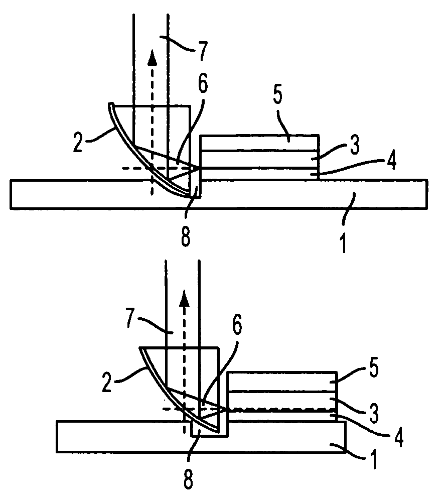
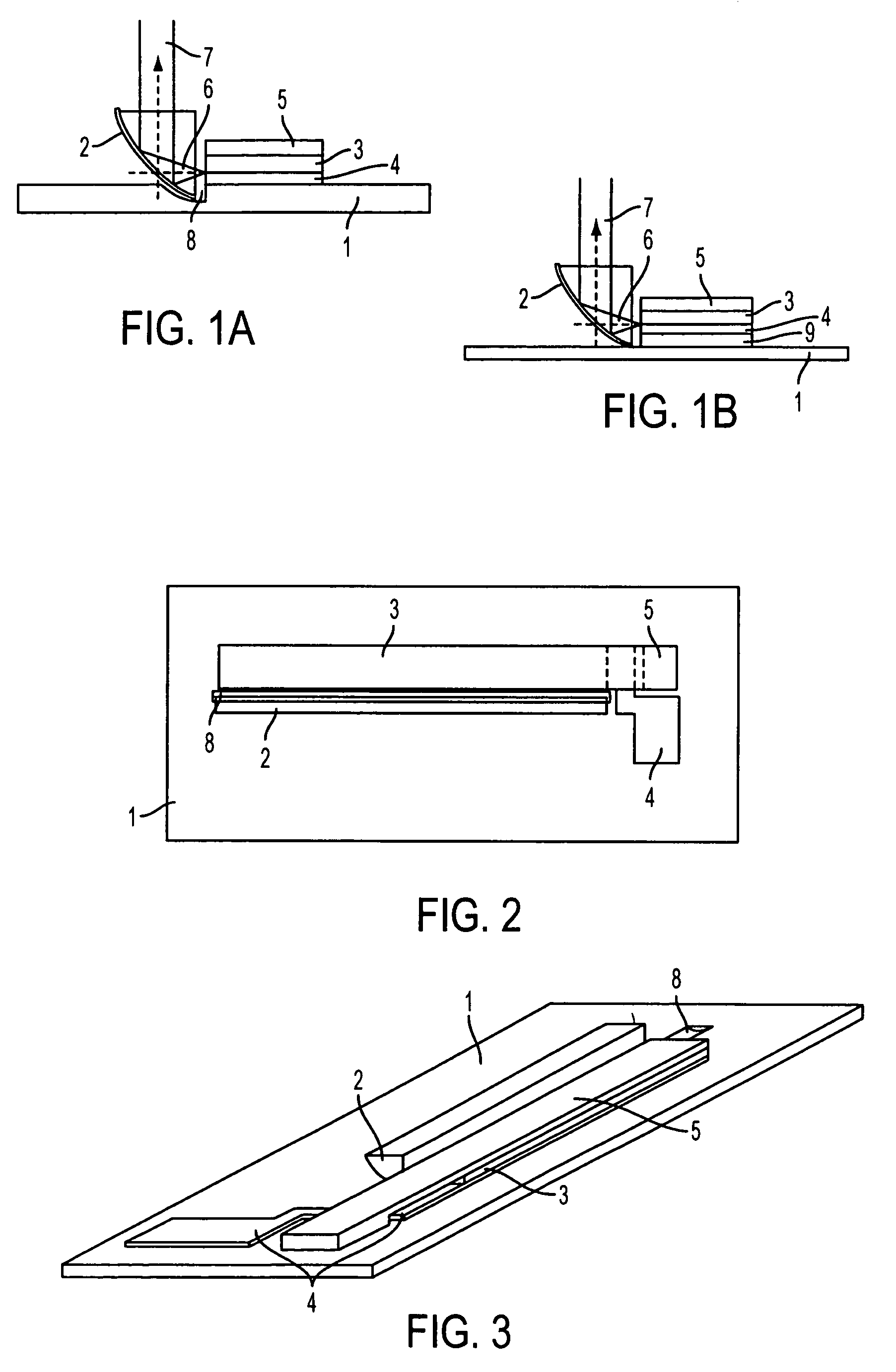
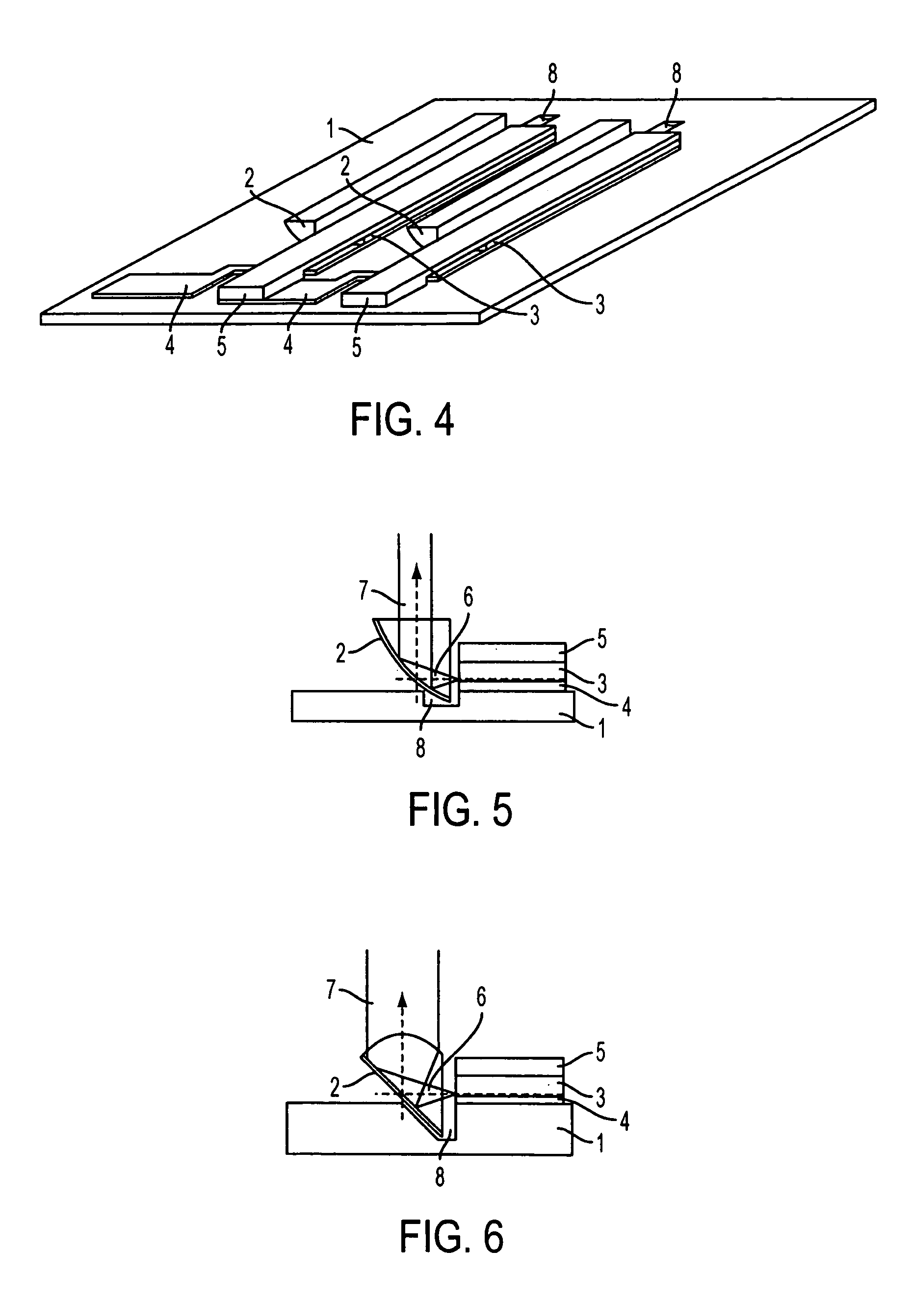
[0046]The subject invention relates to the use of a beam control prism for redirecting, and / or modifying the beam characteristics of, one or more sources of light. Such sources of light can include, for example, laser diodes, laser diode arrays, and / or diode bars. In a specific embodiment, the source of light can emanate from a diode bar mounted on a substrate.

[0047]The use of a prism with a reflective surface can enable the mounting of an edge emitting laser diode on a flat surface. Surface mounted construction can be simpler and can provide for better thermal management of the diodes, compared to conventional stack mounting technology. A specific embodiment of the subject invention is shown in FIG. 1A. This embodiment incorporates a reflective prism 2 mounted on an electrically insulated, thermally conductive substrate 1 next to an edge emitting laser diode 3. An electrical conductor 4 is applied on top of the substrate 1 to provide one of the electrical connections to the diode 3...


PUM


Abstract

The subject invention relates to beam control prisms and the use of a beam control prism to modify the beam properties of light emitted from an edge emitting diode laser. The subject invention can utilize a beam control prism placed next to a diode laser bar. The subject beam control prism can have, for example, a curved surface and/or a high reflective coated surface for a diode laser wavelength. The curved surface can collimate the fast axis divergence and the mirror surface can change the beam direction. The subject curved surface beam control prisms can incorporate one or more features, such as parabolic reflecting surface, elliptical exit surface with flat reflecting surface, and a hyperbolic entrance surface with flat reflecting surface.

Description

CROSS-REFERENCE TO A RELATED APPLICATION[0001]This application claims priority from provisional patent application U.S. Ser. No. 60 / 369,781, filed Apr. 3, 2002.BACKGROUND OF INVENTION[0002]Keeping diode lasers cool is a major concern for most diode laser applications. For high power diode laser arrays, thermal management is a critical concern. Modern diode laser array designs can generate a heat flux greater than 400 W / cm2. The traditional way for packaging an edge emitting diode array is by stacking the diode lasers vertically with cooling and electrical connection plates sandwiched in between. The diode active area, which generates tremendous amount of waste heat, is a considerable distance from the coolant in the traditional design. Also, several layers of solder and an electrical insulation layer must be used resulting in additional thermal resistance. This design results in a longer cooling path than is desirable in order to maintain uniform cooling for all diodes. The longer c...

Claims


Application Information

Patent Timeline
Patent Type & Authority Patents(United States)
IPC IPC(8): G02B5/04G02B27/09G02B27/14H01S3/08H01S5/18
CPCG02B27/0972H01S5/4062G02B19/0057G02B19/0028H01S5/005H01S5/0071H01S5/4081
Inventor CHUNG, TE-YUANBASS, MICHAELRINI, DANIEL P.ANDERSON, H. RANDOLPHCHOW, LOUIS
Owner UNIV OF CENT FLORIDA RES FOUND INC
Why Eureka
Try Eureka