Supercharging unit for an internal combustion engine, and internal combustion engine

Active Publication Date: 2015-08-13
ROLLS ROYCE SOLUTIONS GMBH
View PDF3 Cites 3 Cited by
  • Summary
  • Abstract
  • Description
  • Claims
  • Application Information

AI Technical Summary

Benefits of technology

[0006]The current invention provides a supercharging unit and an internal combustion engine wherein the supercharging unit features an especially compact design and an esp

Problems solved by technology

It has been shown that this arrangement requires a comparatively large space whereby also the f

Method used


Image

  • Supercharging unit for an internal combustion engine, and internal combustion engine
  • Supercharging unit for an internal combustion engine, and internal combustion engine

Examples


Embodiment Construction

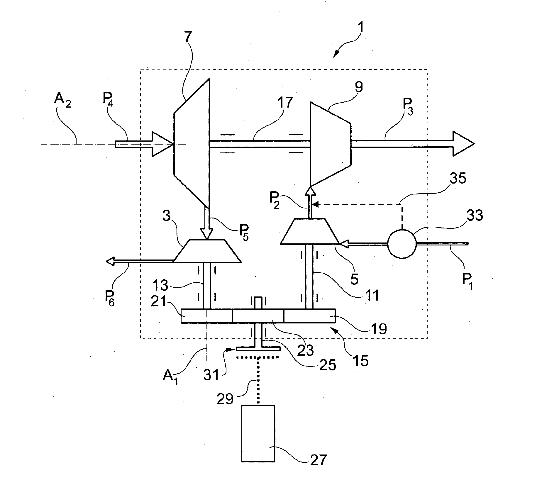
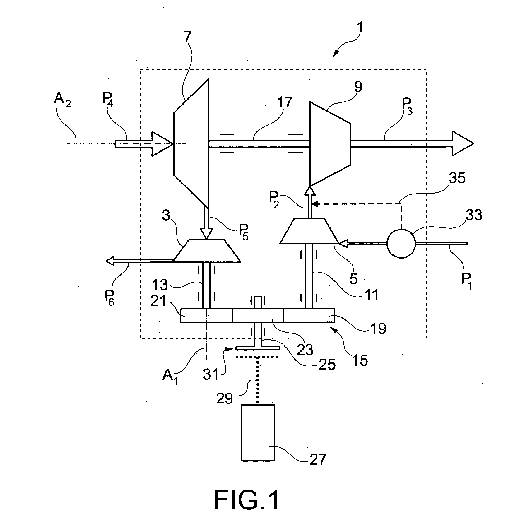
[0026]FIG. 1 is a schematic illustration of a supercharging unit 1 which includes a high pressure compressor 3 which can be driven by a high pressure turbine 5 to perform a rotational movement around a first axis A1.

[0027]Moreover, a low pressure compressor 7 is provided which can be driven by a low pressure turbine 9 to perform a rotational movement around a second axis A2.

[0028]Exhaust gas flowing from an internal combustion engine which is not illustrated here—as illustrated by an arrow P1—is first supplied to high pressure turbine 5 through which it flows, thereby powering high pressure turbine 5. From there is directed on, along a path P2 and is supplied to low pressure turbine 9 through which it flows, thereby powering it. From there it flows—as illustrated schematically by an arrow P3—to an exhaust gas system which is not illustrated and not discussed here in further detail. High pressure turbine 5 and low pressure turbine 9 are therefore series connected, viewed in flow dire...


PUM


Abstract

A surpercharging unit for an internal combustion engine has a high-pressure turbine which drives a high-pressure compressor so as to perform a rotational movement about a first axis and through which exhaust gas of the internal combustion engine flows, and having a low-pressure turbine which drives a low-pressure compressor so as to perform a rotational movement about a second axis and through which exhaust gas flows. The high-pressure turbine is arranged rotationally conjointly on a first shaft, and the high-pressure compressor is arranged rotationally conjointly on a second shaft, wherein the first and the second shaft are arranged parallel to one another and are arranged offset with respect to one another, wherein the first and the second shaft are mechanically operatively connected to one another such that the high-pressure compressor can be driven by the high-pressure turbine.

Description

CROSS REFERENCE TO RELATED APPLICATIONS[0001]This is a continuation of PCT application No. PCT / EP2013 / 003183, entitled “SUPERCHARGING UNIT FOR AN INTERNAL COMBUSTION ENGINE, AND INTERNAL COMBUSTION ENGINE”, filed Oct. 22, 2013, which is incorporated herein by reference.BACKGROUND OF THE INVENTION[0002]1. Field of the Invention[0003]The current invention relates to internal combustion engines, and, more particularly, to a supercharging unit for use with an internal combustion engine.[0004]2. Description of the Related Art[0005]Supercharging units for combustion engines and for combustion engines of the type specified here are known in the current state of the art. Such a supercharging unit is driven by exhaust gas flowing from the internal combustion engine and serves to compress the charging air supplied to the internal combustion engine. Two-stage supercharging units which include a high pressure and a low pressure component serve to increase the efficiency of compression and to be...

Claims


Application Information

Patent Timeline
IPC IPC(8): F02B37/013F02B37/18F02B37/10F02B37/00
CPCF02B37/013F02B37/10F02B37/18F02B37/004F02B39/04F02B39/10Y02T10/12
Inventor HEGNER, RONALD
Owner ROLLS ROYCE SOLUTIONS GMBH
Why Eureka
Try Eureka