Portable radio unit

A radio unit, portable technology, applied in the direction of electrical components, electrical components, electrical equipment casings/cabinets/drawers, etc., can solve the problems of inconvenient feeder setting, reduced antenna efficiency, and complicated mechanism.

Inactive Publication Date: 2005-05-04
MITSUBISHI ELECTRIC CORP
View PDF2 Cites 3 Cited by
  • Summary
  • Abstract
  • Description
  • Claims
  • Application Information

AI Technical Summary

Problems solved by technology

[0004] However, in the wireless communication device disclosed in the above document, there are substantially two antennas on the cover, and the combination of these antennas may lower ...

Method used


Image

  • Portable radio unit
  • Portable radio unit
  • Portable radio unit

Examples


Embodiment approach 1

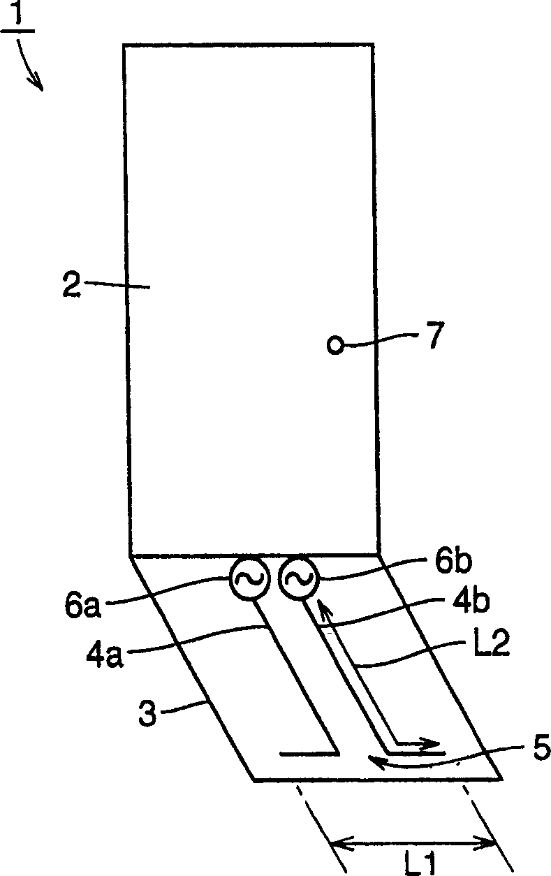
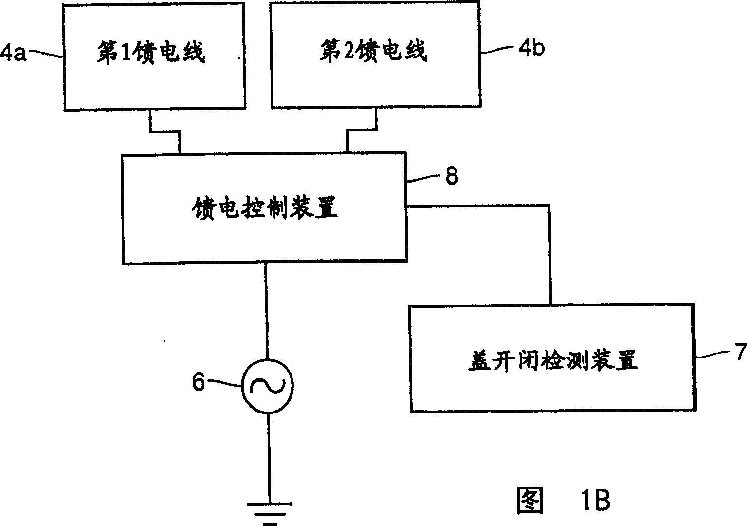
[0038] Such as Figure 1A As shown, the portable radio unit 1 has a casing 2 (ground conductor), a cover (flip cover) 3 that can be opened and closed freely, a dipole antenna 5, a first and a second feeder 4a, 4b, an RF (Radio Frequency) power supply 1 and the second power supply 6a, 6b and the cover opening and closing detection device 7.

[0039] The cover 3 is openably and closably attached to the case 2, is made of, for example, a dielectric material such as an organic polymer, and has a dipole antenna 5 inside. The dipole antenna 5 has a length L1 of one-half wavelength (λ / 2), and extends in a direction perpendicular to the long direction of the housing 2 . As a result, when the housing 2 is tilted to make a call, the polarized wave component perpendicular to the ground increases, and the consistency with the base station of the vertically polarized wave becomes better.

[0040] The first and second feeding lines 4a, 4b and the first and second power sources 6a, 6b oper...

Embodiment approach 2

[0049] Next, use Figure 3A and 3B Embodiment 2 of the present invention and its improvements will be described.

[0050] Such as Figure 3A As shown, in Embodiment 2 of the present invention, the tip of the dipole antenna 5 is bent. Thereby, the physical length of the dipole antenna 5 can be shortened, and the dipole antenna 5 can be made more compact. other structures and Figure 1A The same applies to the first embodiment shown.

[0051] In addition, as shown in FIG. 3 , the top end of the dipole antenna 5 can also be bent into a serpentine shape. In this case also, the same effect can be obtained.

Embodiment approach 3

[0053] Next, use Figure 4A and Figure 4B Embodiment 3 of the present invention will be described. Such as Figure 4A As shown, in Embodiment 3, the coaxial line 9 is used as the feeder. The coaxial line 9 has an outer conductor 9a and an inner conductor 9b, and the outer conductor 9a is short-circuited to the case. That is, the outer conductor 9a is grounded.

[0054] Coaxial lines 9, such as Figure 4B As shown, it is arranged to be spaced from the casing, and one end of the external conductor 9a is short-circuited with the casing 2 at the short-circuit point 11. In addition, if Figure 4A and Figure 4B As shown, the interval L3 between the feeding point 10 of the outer conductor 9a and the above-mentioned short-circuit point 11 is approximately λ / 4. Thereby, since the estimated impedance from the power source 6 a to the short-circuit point 11 becomes infinite, it is possible to suppress the influence of the short-circuit point 11 on the impedance of the feeding po...


PUM


Abstract

The portable type radio unit possesses three portions of part and functions. The first portion includes case, a cover possible to be opened and closed freely installed on the case, a bipolar antenna on the cover, feeder apparatus for feeding the bipolar antenna, and controller for controlling feeder apparatus based on closing or opening state of the cover to control the feeder apparatus. The second portion includes resonator setup on the case. When the cover is closed, the resonator is located near to place of the bipolar antenna. The third portion provides function of switching connection of first or second matching circuit with the feeder apparatus and the bipolar antenna based on closing or opening states.

Description

technical field [0001] The present invention relates to a portable radio unit, and more particularly to a portable radio unit having an antenna provided on an openable and closable housing portion (hereinafter referred to as a cover). Background technique [0002] Japanese Unexamined Patent Publication No. 8-186518 discloses an example of a wireless communication device having an antenna on an openable cover. [0003] The aforementioned cover antenna has first and second components, the first component is tuned to the operating frequency of the receiving and transmitting circuit when the cover is opened, and the second component is tuned to the operating frequency of the receiving and transmitting circuit when the cover is closed. Therefore, regardless of whether the cover is open or closed, the cover antenna can be tuned to the operating frequency of the receiving and transmitting circuits. [0004] However, in the wireless communication device disclos...

Claims


Application Information

Patent Timeline
IPC IPC(8): H05K5/00H05K11/00
Inventor 东海林英明今西康人深泽彻大岭裕幸
Owner MITSUBISHI ELECTRIC CORP
Why Eureka
Try Eureka