Multiband-support radio-frequency module

a radio-frequency module and multi-band technology, applied in waveguide type devices, frequency selective two-port networks, amplifier modifications to reduce non-linear distortion, etc., can solve the problems of reduced radio-frequency modules, ground electrodes that cannot perform their functions properly, and high-output radio-frequency output, etc., to achieve excellent rf characteristics and excellent rf characteristics

Active Publication Date: 2016-08-09
MURATA MFG CO LTD
View PDF10 Cites 4 Cited by
  • Summary
  • Abstract
  • Description
  • Claims
  • Application Information

AI Technical Summary

Benefits of technology

[0008]In accordance with a reduced size of communication mobile terminals, there is also a demand for further reducing the size of the radio-frequency module 500 mounted on such a communication mobile terminal. However, reducing the size of the radio-frequency module 500 presents the following problem. For reducing the size of the radio-frequency module 500, the size of the multilayer substrate 501 is also decreased. Accordingly, the physical length of a signal path between the power amplifier PA and the diplexer DPX disposed in each of the regions A and B of the multilayer substrate 501 is reduced, and thus, the signal paths 502 and 503 are wired with a minimal distance. The distance by which the loss incurred by wiring is minimized is called a minimal distance. Additionally, ground electrodes disposed for the power amplifier PA and for the diplexer DPX in the multilayer substrate 501 are also reduced in size.
[0027]According to the present invention, high-output radio-frequency signals output from the first and second amplifier circuits can be prevented from respectively interfering with the first and second filter circuits and the first and second signal paths disposed in the multilayer substrate. It is thus possible to provide a multiband-support radio-frequency module exhibiting excellent RF characteristics by suppressing the occurrence of harmonic signals in each of the first and second amplifier circuits and by preventing the output of radio-frequency signals containing unwanted harmonic components.

Problems solved by technology

However, reducing the size of the radio-frequency module 500 presents the following problem.
In accordance with a reduced physical length of the signal path between the power amplifier PA and the diplexer DPX, the ground electrodes are also reduced in size, and thus, the ground electrodes are unable to perform their function properly.
This causes a problem in which a high-output radio-frequency output from the power amplifier PA interferes with various components including the diplexer DPX and wiring electrodes disposed in the multilayer substrate 501.
This causes a problem in which the RF characteristics of the radio-frequency module 500 are decreased.

Method used


Image

  • Multiband-support radio-frequency module
  • Multiband-support radio-frequency module
  • Multiband-support radio-frequency module

Examples


first embodiment

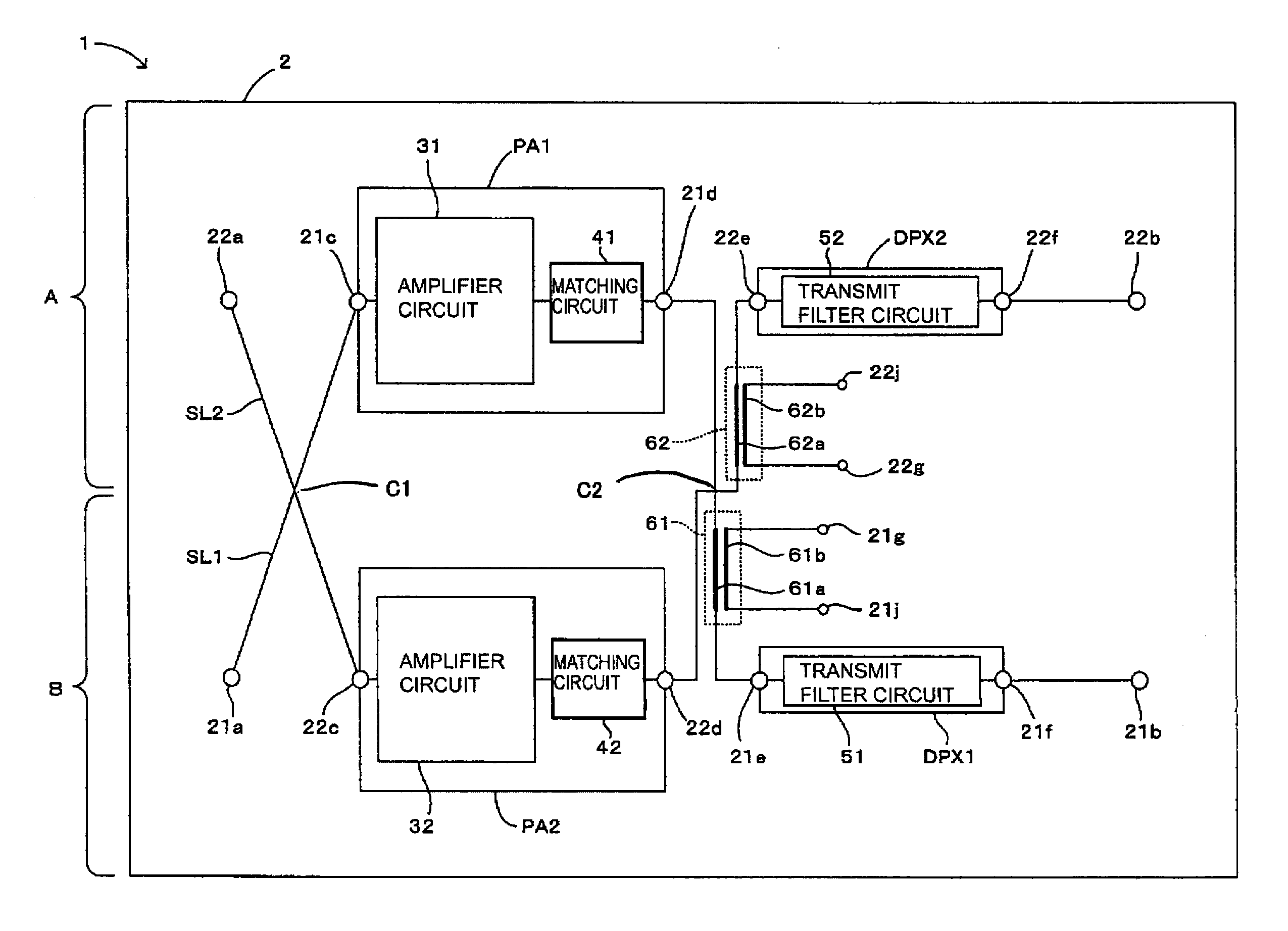
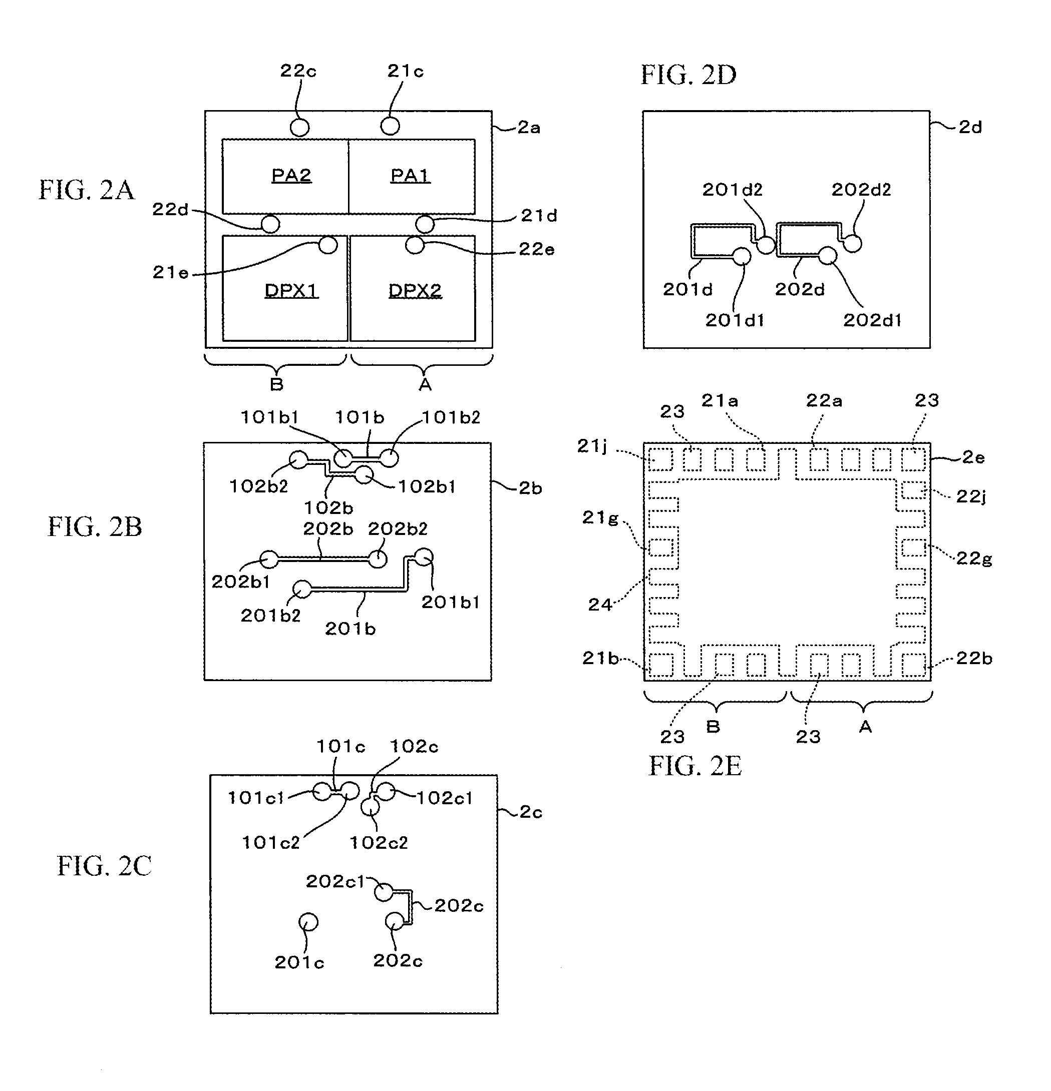
[0041]A first embodiment of a radio-frequency module according to the present disclosure will be described below with reference to FIGS. 1 through 5. FIG. 1 is a diagram illustrating the first embodiment of a radio-frequency module of the present invention. FIGS. 2A to 2E show plan views illustrating insulating layers of a multilayer substrate included in the radio-frequency module shown in FIG. 1. FIGS. 2A to 2E illustrate the different insulating layers. FIGS. 3A and 3B show diagrams illustrating a first signal path and a second signal path, as viewed from above. FIG. 3A illustrates the signal paths prior to amplifier circuits, and FIG. 3B illustrates the signal paths subsequent to the amplifier circuits.

[0042]FIGS. 4A and 4B show diagrams illustrating the power density of harmonic components contained in a radio-frequency signal output from the first signal path of the radio-frequency module shown in FIG. 1. FIG. 4A illustrates the power density of second harmonic components, and...

second embodiment

[0080]A second embodiment of a radio-frequency module of the present disclosure will be described below with reference to FIG. 6. FIG. 6 is a diagram illustrating the second embodiment of a radio-frequency module of the present invention.

[0081]A radio-frequency module 1a of this embodiment is different from the radio-frequency module 1 of the above-described first embodiment in the following configuration. As shown in FIG. 6, a third filter circuit 71 is disposed in the first signal path SL1, and a fourth filter circuit 72 is disposed in the second signal path SL2. The other configurations of the second embodiment are similar to those of the above-described first embodiment, and thus, they are designated by like reference numerals and an explanation thereof will be omitted.

[0082]The third and fourth filter circuits 71 and 72 may be formed as band-pass filters, as in the above-described first and second transmit filter circuits 51 and 52, or may be formed as band-elimination filters....

third embodiment

[0085]A third embodiment of a radio-frequency module of the present disclosure will be described below with reference to FIG. 7. FIG. 7 is a diagram illustrating the third embodiment of a radio-frequency module of the present invention.

[0086]A radio-frequency module 1b of this embodiment is different from the radio-frequency module 1 of the above-described first embodiment in the following configuration. As shown in FIG. 7, in an area prior to the first and second power amplifiers PA1 and PA2, the first and second signal paths SL1 and SL2 do not intersect each other. The other configurations of the third embodiment are similar to those of the above-described first embodiment, and thus, they are designated by like reference numerals and an explanation thereof will be omitted.

[0087]With this configuration, too, advantages similar to those of the above-described embodiment can be obtained.

[0088]In this embodiment, too, the above-described first and second directional couplers 61 and 62...


PUM


Abstract

To provide a multiband-support radio-frequency module in which the occurrence of a harmonic signal in an amplifier circuit is suppressed and the output of a radio-frequency signal containing unwanted harmonic components is prevented. A first signal path SL1 and a second signal path SL2 are provided such that they intersect each other at least once in a multilayer substrate 2, as viewed from above. With this configuration, high-output radio-frequency signals output from a first amplifier circuit 31 and a second amplifier circuit 32 can be prevented from interfering with other elements disposed in the multilayer substrate 2. It is thus possible to provide a multiband-support radio-frequency module 1 exhibiting excellent RF characteristics by suppressing the occurrence of harmonic signals in each of the first and second amplifier circuits 31 and 32 and by preventing the output of radio-frequency signals containing unwanted harmonic components.

Description

FIELD OF THE DISCLOSURE[0001]The present disclosure relates to a radio-frequency module including a multilayer substrate having a first signal path through which a radio-frequency signal of a first frequency band passes and a second signal path through which a radio-frequency signal of a second frequency band passes.DESCRIPTION OF THE RELATED ART[0002]Hitherto, as shown in FIGS. 13A and 13B, there is provided a multiband-support radio-frequency module 500 including a multilayer substrate 501 having a plurality of signal paths through which transmitting signals (radio-frequency signals) of different frequency bands pass. FIGS. 13A and 13B illustrate known modules, and are respectively a plan view and a circuit block diagram of the known modules. The radio-frequency module 500 includes a first signal path 502 through which a transmitting signal of the 800 MHz band passes and a second signal path 503 through which a transmitting signal of the 1.9 GHz band passes. In each of the signal ...

Claims


Application Information

Patent Timeline
Patent Type & Authority Patents(United States)
IPC IPC(8): H01P5/12H03F3/213H03F3/195H03H11/04H03F3/24H03F1/32H04B15/06H03F3/19H03F3/21H03F3/60H03H9/05
CPCH03F1/32H04B15/06H03F3/195H03F3/213H03F3/245H03F3/60H03F3/19H03F3/21H03H11/04H03F2200/111H03H9/0566H03F2200/222H03F2200/451
Inventor TAKEMATSU, YUJI
Owner MURATA MFG CO LTD
Why Eureka
Try Eureka